SOLIDWORKS FeatureWorks: Automatic vs. Interactive Recognition
What is FeatureWorks?
FeatureWorks is an integrated geometry recognition module that allows for files imported to SOLIDWORKS from other CAD systems (Inventor, Pro/Engineer, CATIA, etc.) to be given a rudimentary feature history where they otherwise would be left simply as an “imported” body. This also has applications when attempting to collaborate with other SOLIDWORKS users who operate on previous versions of SOLIDWORKS where newer version files are not able to be opened and edited within the past version of SOLIDWORKS.
Allowing FeatureWorks to create a feature tree enables a SOLIDWORKS user to make parametric model edits that are routine with SOLIDWORKS. While the FeatureWorks module may not recognize complex geometry or create the exact feature tree a user desires it is still a powerful tool in modifying designs.
Automatic Mode vs Interactive Mode
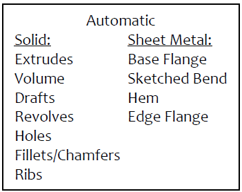
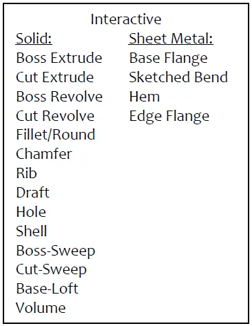
FeatureWorks comes with two main modes; “Automatic” and “Interactive.” The difference between automatic and interactive modes is not only in the behavior but also in the complexity of geometry that can be recognized. As seen in the lists below, interactive mode allows sweep, loft, and shell feature recognition where automatic mode does not. Alternatively, automatic mode, through lack of required input from the user has the advantage of speed.
The differences in permitted features aside, the ability of interactive mode to allow a user to determine the build order of recognized features allows it to succeed where automatic mode may otherwise fail.
The examples provided in this document will show the difference in outcomes of automatic recognition versus interactive recognition modes to show the abilities and limitations of each.
Example of Automatic mode
In this example, a body is imported from an .IGES neutral file. ‘Import Diagnostics’ is triggered by opening a non-native file format. It is recommended to always run import diagnostics to ensure the model is clean geometrically but will not be covered here. Following this FeatureWorks recognition software is immediately prompted to begin. Replying ‘Yes’ begins the process.
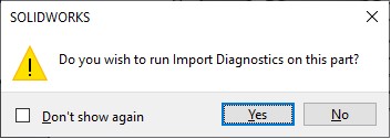
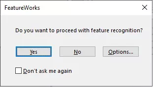
Figure 1: Examples of the import diagnostics and feature recognition prompts
In the property dialog that appears on the left-hand side of the graphics window, shown in Figure 2a, ‘Automatic’ mode is selected. In this case, only solid features are selected for recognition as the model is not thin-walled and would not be represented by sheet metal very well. With the options for ‘Extrudes’, ‘Drafts’, ‘Revolves’, ‘Holes’, ‘Fillets/Chamfers’, and ‘Ribs’ turned on all that is required to proceed is to press the blue right-arrow at the top of the dialog.
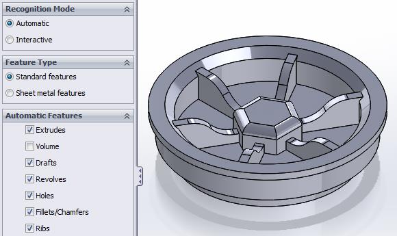
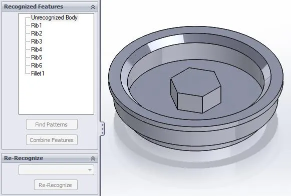
Figure 2a: Automatic recognition settings Figure 2b: Result of automatic recognition showing unrecognized geometry
As illustrated above in Figure 2b, automatic mode runs the risk of not recognizing parts of an imported body. While these portions of the imported body may seem simple, without assistance from a user they are left unrecognized and unsolved by the software.
Should the model fail to be fully recognized in this way the user can use the blue left-arrow at the top of the property dialog to return to the recognition options and try again. Only the unrecognized portion of the model will be sent through the recognition module; recognized features will be removed from further calculations. In this way, successive attempts using the automatic recognition mode may eventually fully recognize a model (this is not always true though).
Example of Interactive mode
In this example, the same body is imported from an .IGES neutral file. ‘Import Diagnostics’ is triggered and ignored and FeatureWorks is again prompted and activated.
In the property dialog that appears on the left-hand side of the graphics window ‘Interactive’ mode is selected. In this case, sheet metal features are again ignored but now the settings have changed to allow for only one type of feature to be recognized at a time. In this way, the user specifies a particular feature type to recognize and manually selects faces to attempt the recognition on.
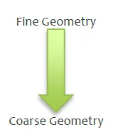
This has the effect of having very granular control over what order features are recognized and what exact features are used on certain parts of the model. What features are recognized first is now an issue. Fine details of a model should be recognized first and the large coarse portions of the geometry later. This is because the finer details can interfere with recognition at times. The following is a general sequence to follow:
- Chamfers/Fillets/Rounds (in order of increasing size)
- Drafts
- Holes
- Ribs
- Cut Extrude/Revolve/Sweep
- Shell
- Boss Extrude/Revolve/Sweep/Loft
Using the same imported body as in the automatic recognition example the process would proceed like this:
- First come the filets. Set ‘Feature Type’ to “Fillet/Round”, turn on “Chain fillet faces”, and select one of the fillet faces; the adjacent fillets will be selected as shown in Figure 3a. Upon pressing “Recognize” the fillet faces are removed and underlying geometry is revealed as shown in Figure 3b.
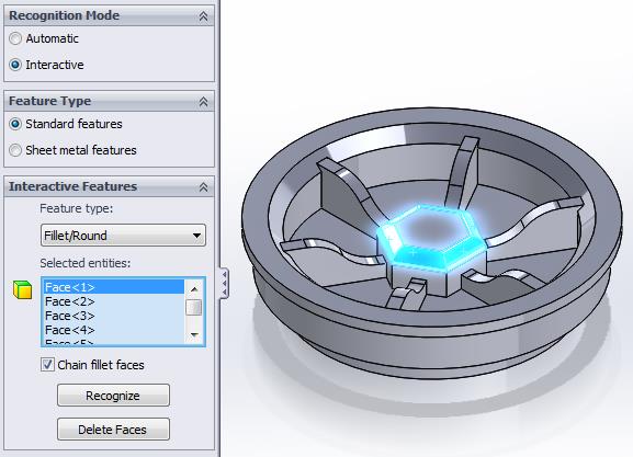
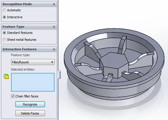
Figure 3a: Fillet recognition settings Figure 3b: Result of fillet recognition - With the fillet out of the way next come the ribs. Set ‘Feature Type’ to “Ribs”, turn on “Recognize similar”, and select a face on one of the ribs like shown in Figure 4a. Selecting all the faces on the rib is not necessary, one is enough. Also, selecting faces on the other ribs is not necessary as they are similar enough to the one selected that the “Recognize similar” option will encompass them as well. Upon pressing “Recognize” all ribs are removed as shown in Figure 4b.
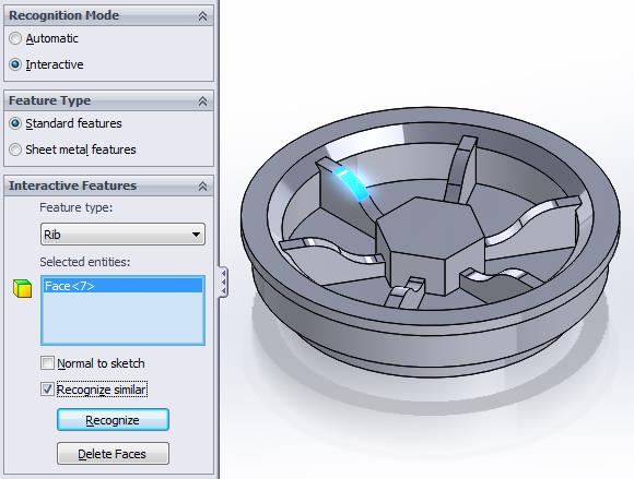
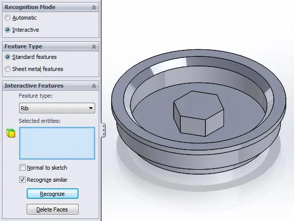
Figure 4a: Rib recognition settings Figure 4b: Result of rib recognition - Next comes the boss extrude. Set ‘Feature Type’ to “Boss Extrude” and select the top face of the hexagonal boss as shown in Figure 5a. Press “Recognize” and the boss is removed as shown in Figure 5b.
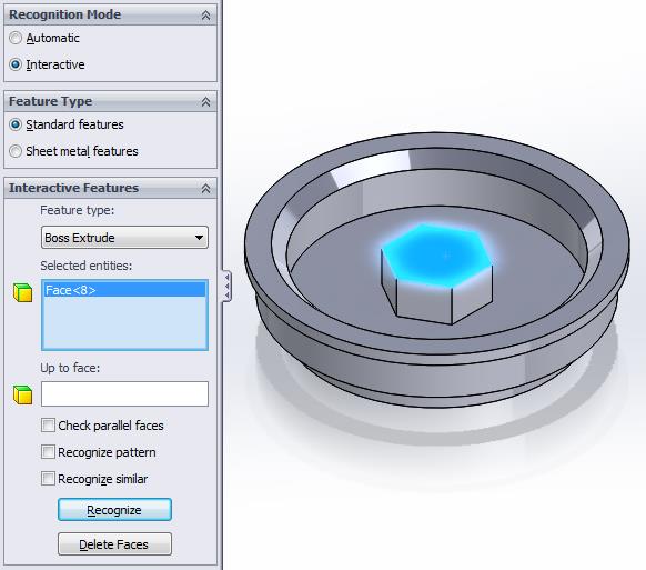
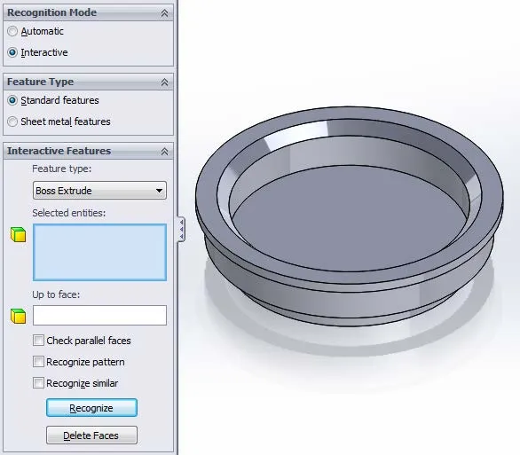
Figure 5a: Boss Extrude recognition settings Figure 5b: Result of Boss Extrude recognition - Next (optionally) comes the chamfer. The chamfer was not done earlier due to interfering geometry from the ribs. Set ‘Feature Type’ to “Chamfer” and select the chamfer face as shown in Figure 6a. Press “Recognize” and the chamfer is removed just like the features before it.
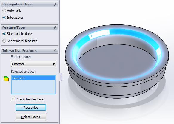
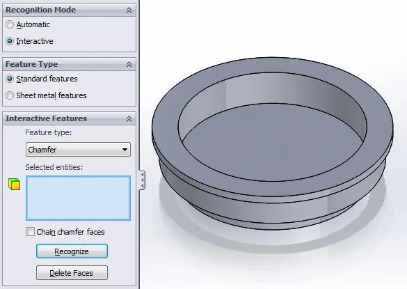
Figure 6a: Chamfer recognition settings Figure 6b: Result of Chamfer recognition - Finally, the geometry is simple enough to be completed with one last recognition. Set ‘Feature Type’ to “Boss Revolve” and select any face as shown in Figure 7a. Press “Recognize” and the body is completely recognized as shown in Figure 7b.
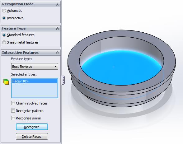
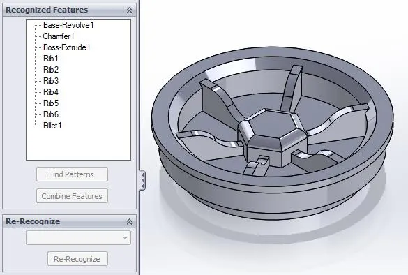
Figure 7a: Chamfer recognition settings Figure 7b: Result of Chamfer recognition
The process is now complete and the entire list of recognized features is listed. Accepting the FeatureWorks command will allow the program to make the final feature tree build of the model; building bottom-up.
Summary
The take away from this is that imported, “dumb,” solids can be made parametric and interactive once again with a small amount of upfront user input. The key to the FeatureWorks Interactive recognition mode is to keep flexible with the recognition order; the goal is a workable feature tree, not a perfect feature tree.
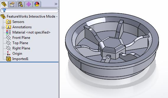
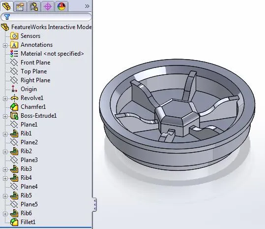
Figure 8a: Beginning with an imported “dumb” solid Figure 8b: Ending with an interactive feature tree
Related Articles
Default SOLIDWORKS File Locations
Planetary Gear Assembly Mates Quick Tip
Using SOLIDWORKS Task Scheduler to Create or Modify Custom Properties

About Ryan Dark
Ryan has been in the GoEngineer technical support team since February 2008 where he most notably provides support for all FEA and CFD software offered by SolidWorks. His most recent accolade is the title of Elite Application Engineer awarded by SolidWorks Corp.
Get our wide array of technical resources delivered right to your inbox.
Unsubscribe at any time.