CST Studio Suite for Electronic Design
Electronic devices are integrated into many product designs. From household appliances, automobiles, and medical equipment to aircraft and mobile devices, electronic circuits are becoming very complex.
These circuits must work in conjunction with other electronic devices while keeping signal integrity (SI) and power integrity (PI). There are also Electromagnetic Compatibility (EMC) standards that must be met. The PCB (printed circuit boards) within the electronic devices will create heat and need to be cooled. Simulation of these designs using CST Studio Suite (developed by Dassault Systèmes) in the development stage will identify problems that can be corrected prior to the start of manufacture.
CST PCB STUDIO
The CST PCB Studio is an electromagnetic simulation tool specifically for the simulation of PCBs. It has the capability to import PCB designs from the most popular EDA layout tools ( Figure 1 ) and incorporates several solver techniques to account for the most important analysis types.
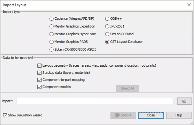
Figure 1: EDA import
Supported import types are:
- ODB++
- Altium
- Cadence
- Mentor Graphics
- Zuken
Design Rule Check
Rule checking allows the user to check the layout for violations with respect to standard EMC (Electromagnetic compatibility) and SI (Signal Integrity) layout rules. This tool quickly identifies traces and layers that violate the rules prior to running simulation studies.
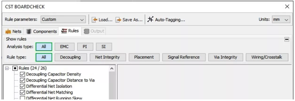
Figure 2: Design Rule Check
Signal Integrity / Power Integrity
In high-speed devices, it is important to check the integrity of the signal paths. (Figure 3) The transmission lines, signal source, and load can be analyzed regarding delay, over and undershoots as well as crosstalk.

Figure 3: Signal Integrity
The goal of a power integrity analysis is to show the impedance (Figure 4) of the power distribution network as seen from component pins. The results of the analysis are the self-impedances measured between pairs of power and ground pins.
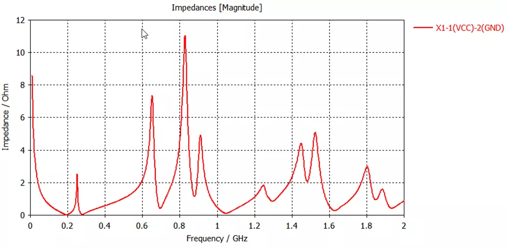
Figure 4: Power integrity Impedances
Electromagnetic Compatibility (EMC)
Electromagnetic Compatibility (EMC) is the ability of an electronic device to operate as designed in its environment without interfering with other devices. Devices must comply with international EMC standards which regulate EM emissions of electrical and electronic systems in order to be sold.
CST Studio Suite gives engineers simulation results relevant to all EMC aspects of a device such as the flow of currents across a circuit board . (Figure 5)

Figure 5: Electromagnetic Compatibility
Thermal Simulation on PCBs
Thermal simulations are run with CST Studio Suite with the CHT (Conjugate Heat Transfer) Solver. This analysis is run based on the IR drop analysis of the PCB layout. It is a coupled simulation where the energy loss is transformed into heat which increases the temperature of the board components. The CHT solver will then compute the temperature increase. The thermal analysis will incorporate the cooling effect of the surrounding air.
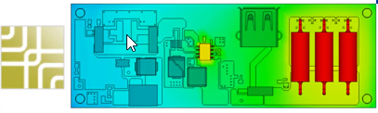
Figure 6: PCB Thermal analysis and Cooling
CST Studio Suite 2023 Buying Guide
Key Features, Applications, Packages, Hardware & more

About Jeff Lendermon
Jeff Lendermon is an Applications Engineer for GoEngineer supporting the SOLIDWORKS Plastics simulation software. Jess has over 30 years of experience in the Plastic Injection molding industry, he applies his experience and knowledge of the industry to help customers see the benefits of utilizing the tools within SOLIDWORKS Plastics.
Get our wide array of technical resources delivered right to your inbox.
Unsubscribe at any time.