Edit Beam Joints in SOLIDWORKS Simulation
SOLIDWORKS Simulation will automatically create beam joints when you create a study with parts created with weldments, or if you treat a solid body as a beam inside of your analysis.
Pink color joints
Where two or more structural members intersect or are coincident, you will see pink color joints. The beams at these joints are bonded to the adjacent beams sharing the same beam joint.
Green color joints
At the free ends of the structural member, you will find light green color joints. These joints are not constrained unless a fixture is added.
However, SOLIDWORKS Simulation may inadvertently calculate a pink joint in an area of your study where you need two beam elements to act independently if you use the All beams option.
In the example below, you can see pink joints at the intersection of the two coincident (non-intersecting) diagonal beams. In this simulation, we do not want these beams bonded together at all.
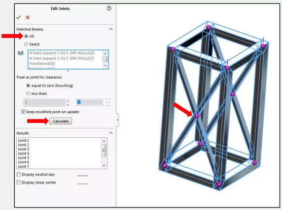
We will now look at how we can manually create and edit the beam joints to provide better control of all of the bodies in the study so we do not over-constrain the model.
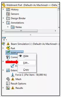
First, right mouse click on the Joint Group item in the simualtion tree and choose Edit…
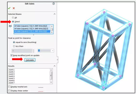
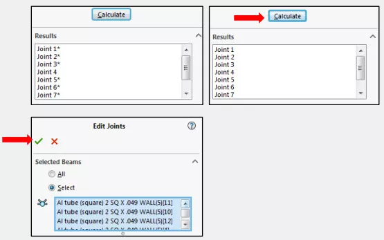
Next, choose the Select option underneath Selected Beams. In the example below, I picked all of the beams (highlighted in blue) except for the four diagonal beams. Then, click Calculate to get the initial joint results. You can see the eight joints calculated below.
Right mouse click on each of the eight joints and select the diagonal beam that you want connected at this joint. In this example, each one of the eight corner joints will need to be modified so we have a total of four beams selected (highlighted in pink). Click the ‘x’ on the Select Joint Members box when complete and move on to the next joint.
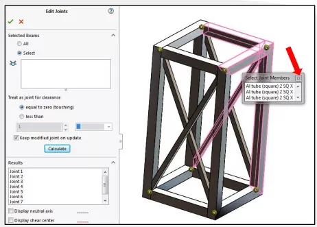
All of the modified joints that need to be recalculated will show up in the results list with an astericks (*). Once you have selected all beams at each joint, click ‘Calculate’. Finally, click on the green check to accept the changes made to the joints in the analysis.
You should now see that each one of the joints is represented with a pink joint. Additionally, there are no joints in the middle of the diagonal beams.
Once you have assigned materials, added fixtures and loads, you can now run your analysis! Below we can observe the difference between the same model with and without the connection at the coincident area between the diagonal beams.
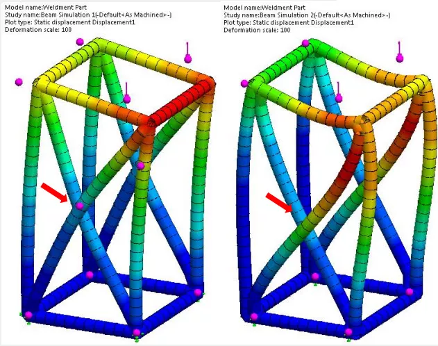
Left: With joint, Right: Without joint
More SOLIDWORKS Simulation Tutorials
Free SOLIDWORKS Simulation Tutorials
SOLIDWORKS Motion Study Analysis and Setup Tutorial
Why Use Hex Elements in Your FEA?
Introduction to Validation Equations in SOLIDWORKS Simulation

About Benjamin Modic
Ben was raised in Metro Detroit and went to school for Mechanical Engineering Technology at Ferris State University. He started using SOLIDWORKS in 2010 while in school after joining the Formula SAE program. After graduation, he spent time working as an engineer in the automotive, sporting goods, and furniture industries in Michigan. Ben moved to Utah to join the GoEngineer team in 2015 and has since focused on leading simulation support for our customers.
Get our wide array of technical resources delivered right to your inbox.
Unsubscribe at any time.