SOLIDWORKS Motion Study Analysis and Setup Tutorial
Motion Analysis is the highest level of SOLIDWORKS Motion Studies. It is available with SOLIDWORKS Premium and any tier of SOLIDWORKS Simulation and grants access to gravity, contact sets, loads, dampers, springs, and motors and allows us to analyze the effects of motion.
This article is a companion to this video which is a demonstration of using Motion Analysis to analyze the motion and loads on the claw assembly pictured below.
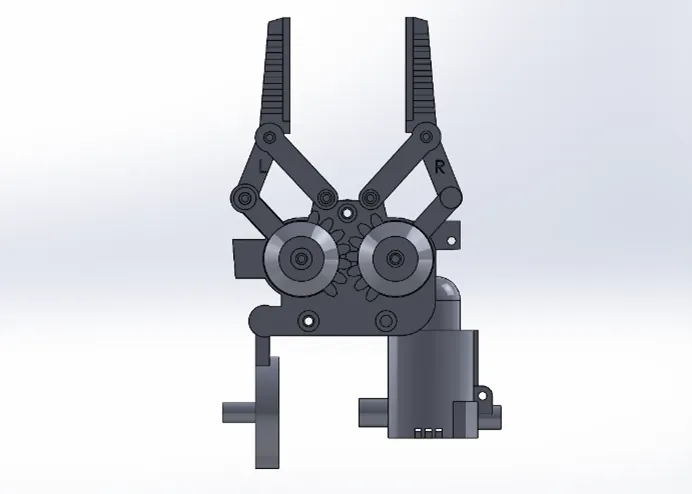
Figure 1: Claw assembly
Setting Up and Running a Motion Study
To create a Motion Analysis study, SOLIDWORKS Motion needs to be enabled in Tools > Add-ins.
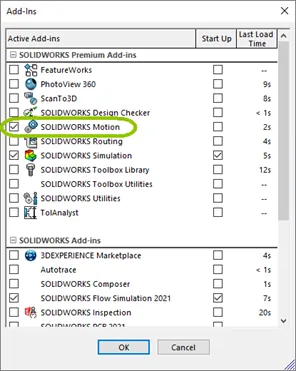
Figure 2: Add-ins pop up dialog
The goal of this Motion Study is to determine the forces on the gear arms when they collide as a result of the gears turning, powered by a rotary motor.
In SOLIDWORKS, this gear assembly has dynamic motion that mimics how it would move in real life thanks to the concentric mates and gear mate applied to it. All mates are imported when a new Motion Study is created.
Because gear mates determine motion based on the radii of selected circular edges and do not take the actual gear teeth into account, the first step we want to take is to suppress the gear mate.
We'll then apply a rotary motor to one of the gears. We need to select the type of motor (Rotary in this example), the location of the motor, and its motion. This example uses a constant speed motor set to 2 RPM.
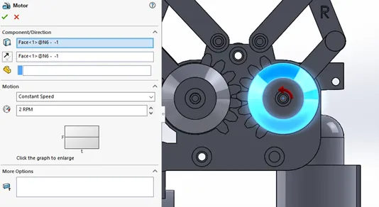
Figure 3: Motor PropertyManager
Now, this gear will move, and we can use that movement to drive the motion of the other gear. For that, we need to set up a component contact.
Click the button for Contact in the MotionManager toolbar. In the Contact PropertyManager, select the Solid Bodies contact type then pick the two gears. The Solid Bodies contact added here prevents the two bodies from passing through each other. We also need to add a component contact to the claws so that they will stop moving when they collide.
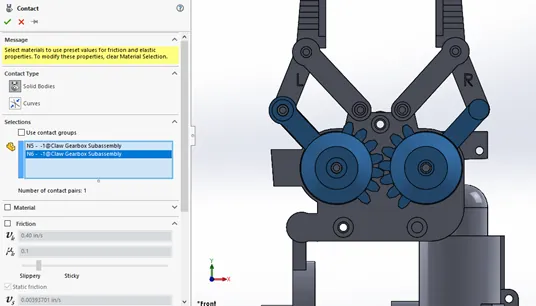
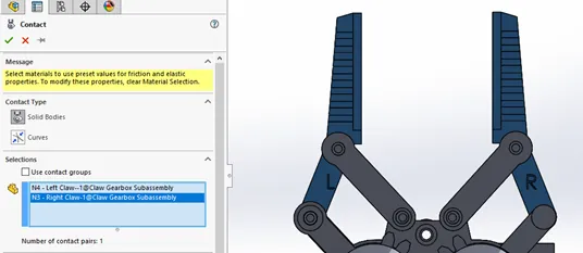
Figure 4: Contact PropertyManagers for gears (top) and claws (bottom)
Click Calculate to run the study. If you've set the animation to play while the study calculates, you'll be able to visually verify that the gears work as intended. When the claws meet, the animation will slow down while their motion is calculated.
Simulating the Effects of Motion
We want to investigate the forces when the claws meet. To determine the moment when this happens, right-click the name of the assembly at the top of the Motion Study tree and select Check interference.
The Find Interference Over Time dialog will pop up. Make sure the time bar is at the end of the animation, then select the two claws and click the Find Now button. The Find interference tool will run through the animation and save any frames in which the selected components are touching or interfering. Clicking any of the resulting time steps will move the time bar to that point.
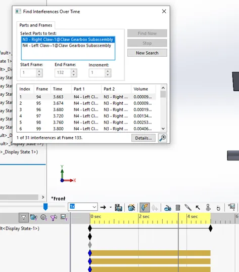
Figure 5: Find Interferences Over Time dialog
To bring this into Simulation, click the Simulation Setup button. In the Simulation Setup PropertyManager, you can enter specific time steps or a time range. Click Add Time then select the components and hit the green check.
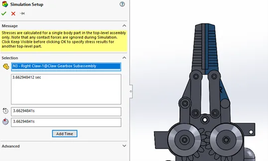
Figure 6: Simulation Setup PropertyManager
Simulation will prompt you to assign a material. In this case, we're selecting Plain Carbon Steel. After applying a material, the Calculate Simulation Results icon activates. Clicking it reruns the motion study to gather the loads.
A results folder appears at the bottom of the tree along with a new key in the Simulation Setup row. Move the time bar to this key to view the results. the result plot icon activates; in the dropdown, you can pick a result plot to save. In the video example, the Isolate tool is used to hide all but the components in which we're interested.
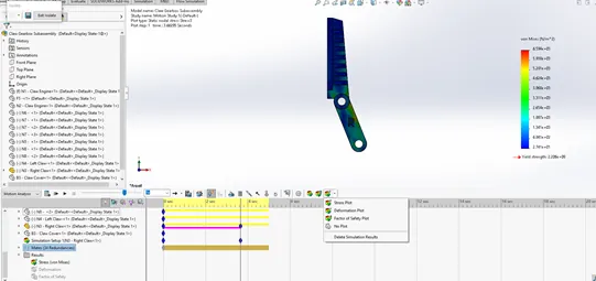
Figure 7: Simulation von Mises Stress Result Plot
Learn More About SOLIDWORKS Motion
Understanding the Rattleback Mystery with SOLIDWORKS Motion
SOLIDWORKS Motion Utilizing Design Studies to Evaluate 'What-if' Scenarios

About Lauren McGarry
Lauren McGarry is a Certified SOLIDWORKS Expert based out of San Diego, California. She earned her Bachelor of Science degree from Case Western Reserve University and has been with GoEngineer as a Technical Support Engineer since 2016.
Get our wide array of technical resources delivered right to your inbox.
Unsubscribe at any time.