Feasibility of Threaded Holes for Rapid Prototyping
When rapid prototyping a component, some of the fine details of the design are sometimes lost. It is common to be asked to print the threads onto tapped holes. The resolution of the printer will often lead to insurmountable issues when printing this geometry creating a lower limit on the hole size that is feasible to print as a tapped hole. In this blog, we discuss the feasibility of threaded holes for rapid prototyping.
Theoretical Thread Geometry
The theoretical shape of a thread profile can be determined by having the Major Diameter (or Minor Diameter), thread pitch (threads per inch), and the given angle of 60 degrees for the triangular profile of the thread.
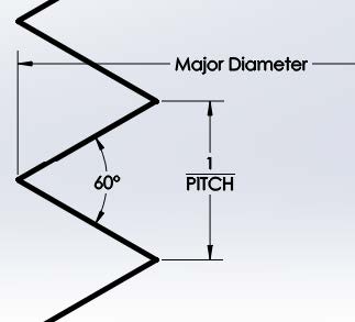
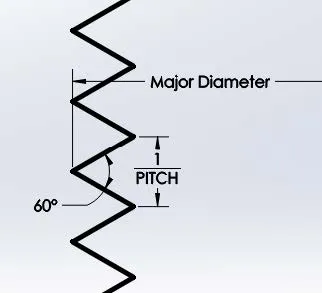
Figure 1: Theoretical cross sections of both a coarse (small pitch) thread and a fine (large pitch) thread.
The difference illustrated in Figure 1 shows that as the thread pitch increases the depth of the threads decreases. For this reason, the thread pitch is the determining factor on whether a threaded hole should be created through 3D printing or created as a post-process to 3D printing.
3D Printed Thread Geometry
The 3D printed geometry of a threaded hole changes from being a smooth continuous thread surface to disjoint strata creating step geometry. Additionally, there are machine accuracy issues that may also come into play. At this time accuracy studies on FDM machines report a 95% confidence window for accuracy of ±0.005 inches in the in-plane print directions (X and Y directions) with a negligible deviation in the printed thickness (Z direction) that can go as low as 0.005 inches.
Vertical Printed Tapped Holes (Z Direction)
As a result of machine limitations, the cross-section of a threaded hole will print similarly to the sections shown in Figure 2. The clear difference between these examples is the number of layers used per thread. Using more printed layers for each thread gives a better representation of the thread than using fewer layers. As a result, the primary concern for Z-direction holes is the layer thickness as compared to the pitch of the threaded hole. The question then becomes, what is the minimum ratio of layers per thread that should be used when 3D printing threads?
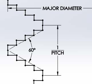
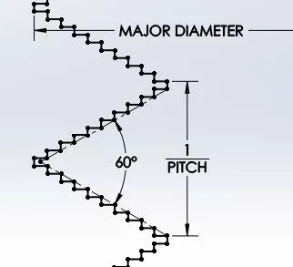
Figure 2: 3D Printed cross sections of both a coarse (small pitch) thread and a fine (large pitch) thread.
Ultimately, each layer of the 3D printed thread must segway from one layer to the next. As the thread pitch is increased the height of each thread approaches the height of each printed layer. It is clear that once the thread height reaches the value of the print thickness that the thread is highly malformed and not representative of a thread any longer. However, a printed thread is not a good representation of the desired theoretical thread long before these values match.
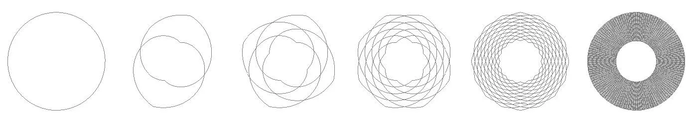
Figure 3: Layer profiles showing 1 layer/thread, 2 layers/thread, 4 layers/thread, 8 layers/thread, 16 layers/thread, and finally a continuous thread profile all seen when viewing down the axis of the threaded hole.
The diagrams shown in Figure 3 shows the overlapping profiles of all layers responsible for a single thread revolution. This is the determining factor in how a printed thread is represented in 3D printing. It can be seen in the diagram that printing anything less than 8 layers/thread does not adequately represent the Minor Diameter of the threaded hole. In an extreme case where a threaded hole is printed at 1 layer/thread (the first object shown in Figure 3), a 3D printer would simply print a straight hole at the value of the Major Diameter.
Horizontal Printed Tapped Holes (X and Y Directions)
Holes printed in the “in-plane” directions of a 3D printer are not affected as heavily by the layer thickness itself as the print resolution itself. As mentioned previously, the X-direction and Y-direction print resolutions can be as low as 0.005 (referred to as a “deviation” for the purposes of this document). This lower limit will impact the quality of holes printed transversely to the printer deck.
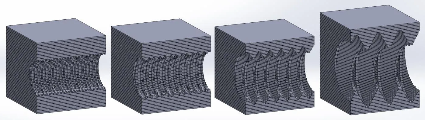
Figure 4: Layer profiles showing 2 threads/deviation, 4 threads/deviation, 8 threads/deviation, and finally 16 threads/deviation.
Figure 4 illustrates how with increasing thread size the thread has a better quality. While even the smallest thread/deviation ratios have some threads along the sizes of the transverse thread the top (+Z direction) and bottom (-Z direction) of the threads are of very low quality. A qualitative assessment of these threads would indicate that having less than 8 threads/deviation gives a low-quality thread. Further, the “noise” introduced to the printed thread by X-direction and Y-direction deviations would disqualify the 2 thread/deviation and 4 thread/deviation models.
A safe estimate would assume thread no smaller than 8 threads/deviation.
Summation of Printed Thread Limitations
The ultimate recommendation of this document is in two main recommendations; one for vertical threads and one for transverse threads
Vertical Thread Lower Limit: 
Horizontal Thread Lower Limit: 
Threads do not always fit perfectly into either of these situations so for all other threads, it is best to calculate both minimum pitch recommendations and use the one that yields the smaller thread pitch.
Alternatives to Printing Threads
For threads that fall outside (or maybe borderline) of the recommended guidelines already presented it is recommended that alternative approaches be made to printing. Some alternatives available are:
Tapping threads: Prior to 3D printing operation the model would be adjusted to change holes with modeled threads to simple clearance or guide holes. Following the normal printing operations, the clearance hole can then be clearance drilled and manually tapped to create a relatively clean set of threads even at higher thread pitches. These threads would likely be purely for aesthetic use as the printed layers would still be cause for structural concerns.
Applying a threaded insert: Prior to 3D printing operations, the model would need to be adjusted so that threaded holes instead replaced with clearance holes in which threaded inserts could be installed post-print. These threaded inserts, usually glued into place, would be the most structurally sound option for putting threads onto a 3D printed model.
Related Articles
3D Printing with the F123 Series: Hardware, Software, and Materials
Fortus Tip and Build Sheet Combinations: 3D Printing Tutorials

About Ryan Dark
Ryan has been in the GoEngineer technical support team since February 2008 where he most notably provides support for all FEA and CFD software offered by SolidWorks. His most recent accolade is the title of Elite Application Engineer awarded by SolidWorks Corp.
Get our wide array of technical resources delivered right to your inbox.
Unsubscribe at any time.