The Power and Value of the SOLIDWORKS Hole Wizard
The SOLIDWORKS Hole Wizard offers various hole options, including threaded holes, clearance holes, pipe threads, dowel holes, and slots. With this tool, you can automatically bring in hole callouts into drawings, have the toolbox match the appropriate fastener size to the hole, and even have SOLIDWORKS automatically populate holes with the correct fastener.
If you don't use the Hole Wizard, you'll have to perform all these actions manually, which can add unnecessary design work that could be better spent on other tasks. It’s time to work smarter, not harder. Keep reading to learn more about the SOLIDWORKS Hole Wizard.
Where is the Hole Wizard Located?
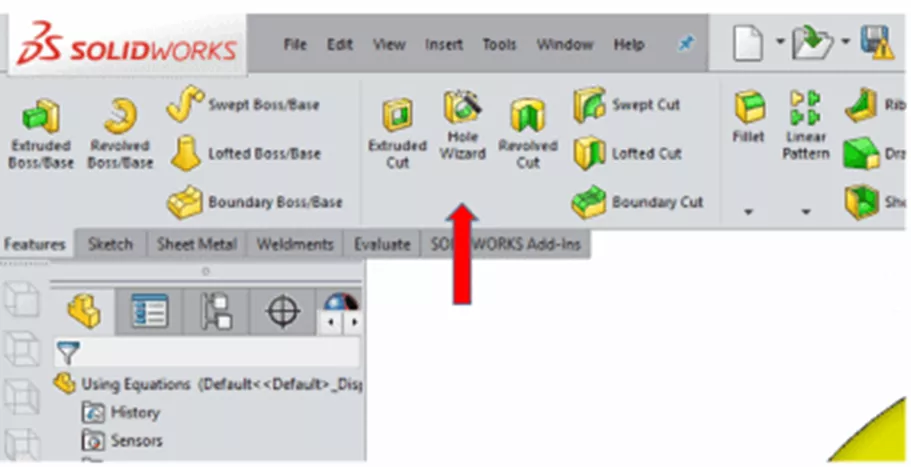
The Hole Wizard tool can be found under the Features tab.
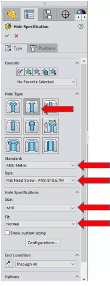
Once activated, the PropertyManager will appear. Select which hole type you want to use, as well as a few other specifications. In this example, I have selected to use a Countersink hole type, and have selected ANSI Metric for my Standard, Flat Head Screw ANSI B18.6.7M for my Type, M10 for the Size, Normal for my Fit, and Through All for my End Condition.
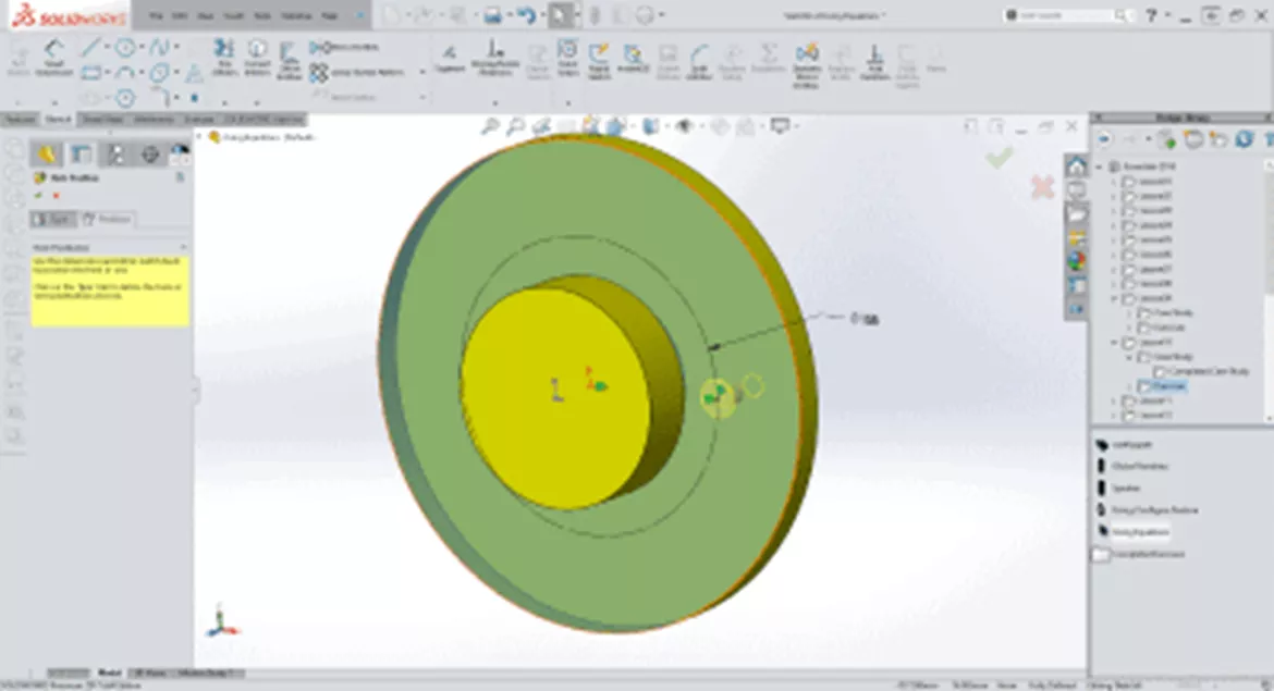
After making your selections, scroll back to the top of the PropertyManager and select the Positions tab. First, select a face on which to place a hole or slot. I have selected the face next to the orange arrow.
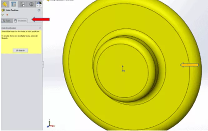
Once a face has been selected, a preview for the hole will appear. Once you have placed your hole, you can start to add relationships and dimensions in order to fully define the hole position.
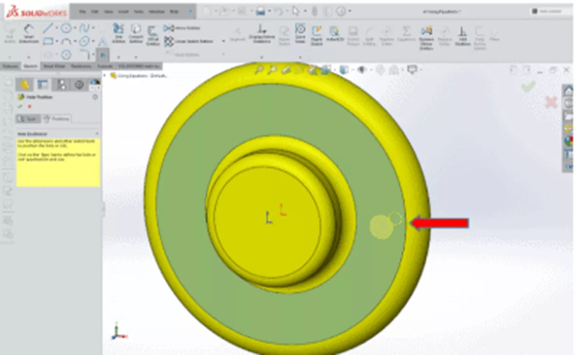
Here, I have a construction circle as a reference, as well as a horizontal relationship to the origin. Once the position for your hole is fully defined, click the checkmark to accept the feature.
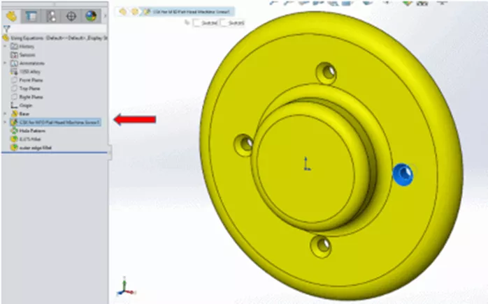
Note: Another advantage to using the SOLIDWORKS Hole Wizard is that the feature is named for you and adds design clarity to the FeatureManager Design Tree. This is very helpful when you need to go back into a design and make design changes.
Creating a Drawing with Hole Wizard Features
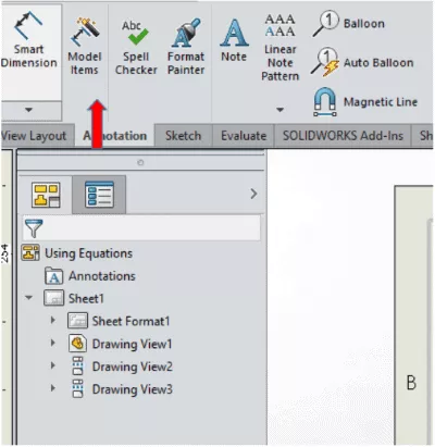
Now that this design is complete, I need to make a drawing. Here is how to leverage the design data from the model and import those dimensions directly into the drawing. First, place the necessary model views into the drawing. Next, select the Model Items tool found under the Annotations tab.
The Model Items PropertyManager is now active. For this example, I am only selecting the hole feature, but you could also bring in all the dimensions for the model by changing the Source from Selected Feature to Entire Model. I have chosen Selected Feature for my Source. Next, I'll select Instance/Revolution Counts, then Hole Wizard Locations, and lastly Hole Callout.

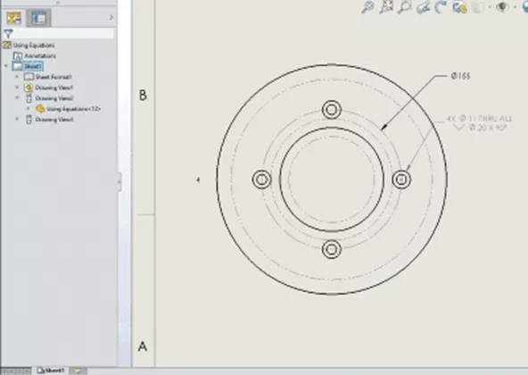
Click the green check mark, and the hole callout, instance count, and pattern diameter will appear in the drawing.
Want to learn more? Check out the articles listed below. Additionally, join the GoEngineer Community to create forum posts, enter design contests, and answer questions from other SOLIDWORKS users.

SOLIDWORKS CAD Cheat Sheet
SHORTCUTS ⋅ MOUSE GESTURES ⋅ HOT KEYS
Our SOLIDWORKS CAD Cheat Sheet, featuring over 90 tips and tricks, will help speed up your process.
Related Articles
How to Fix Hole Wizard & Toolbox File Database Errors in SOLIDWORKS
SOLIDWORKS Hole Wizard Holes at an Angle? Here’s How!
SOLIDWORKS Assembly Hole Series Explained
Getting Started with SOLIDWORKS Hole Tables
![]()
About GoEngineer
GoEngineer delivers software, technology, and expertise that enable companies to unlock design innovation and deliver better products faster. With more than 40 years of experience and tens of thousands of customers in high tech, medical, machine design, energy and other industries, GoEngineer provides best-in-class design solutions from SOLIDWORKS CAD, Stratasys 3D printing, Creaform & Artec 3D scanning, CAMWorks, PLM, and more
Get our wide array of technical resources delivered right to your inbox.
Unsubscribe at any time.