Prescribed Displacement to find Reaction Force in SOLIDWORKS Simulation
SOLIDWORKS Simulation is commonly used on a model with a combination of fixtures and known force loads to find displacement and stress data from such loading conditions. At times though, it is not known what applied force to place on a model whereas the displacement of the model is known and the applied force is the desired quantity to be measured. SOLIDWORKS Simulation is capable of simulating this process as well. In this article, we'll take a look at prescribed displacement to find reaction force in SOLIDWORKS Simulation.
The Setup
The following model is a simple 2D analysis setup of a leaf spring interacting with against a block as shown in figure 1. It is known that the leaf spring should be bent to such a position as to allow the block to pass but it is not known what force applied will allow for this.
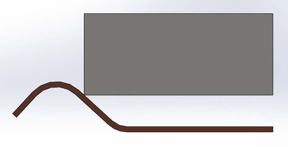
Figure 1: Side view of a leaf spring/block system at initial contact
Given this setup will require a large displacement of both the block and the spring a ‘nonlinear’ type study will be used. However, the same techniques can be applied to ‘static’ type studies provided the prescribed displacement is small enough and stresses remain below material yield points.
Fixtures
In this setup, the far right end of the leaf spring will be fixed in space using a base “Fixed” fixture definition. The far end of the block will likewise have a fixture applied to it but using the ‘Advanced’ fixtures setting. Figure 2 shows the far right edge of the block selected for the fixture where the fixture translations have been set to translate 1” horizontally and 0” vertically. Both directions require restraint for the analysis to be stable, hence the 0” vertical displacement portion of the definition.
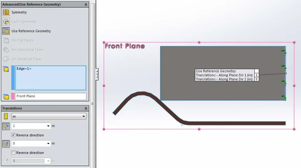
Figure 2: Definition settings for the advanced, ‘Use Reference Geometry’ fixture used to create the prescribed displacement in the analysis
Loads
There are no loads in this analysis given that the prescribed displacement used to push the two bodies together will be causing a load on the models.
Contacts
A single “No Penetration” contact set is defined between the faces of the leaf spring and the corresponding faces of the block to allow the analysis to push the bodies together while allowing for sliding in the contact region.
Results
The resulting stress (Figure 3) and displacement (Figure 4) plots confirm the block pushing the leaf spring out of position as well as showing significant bending stress in the leaf spring near the location where the leaf spring itself is fixed.
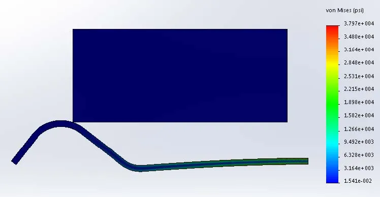
Figure 3: Stress plot generated from the prescribed displacement
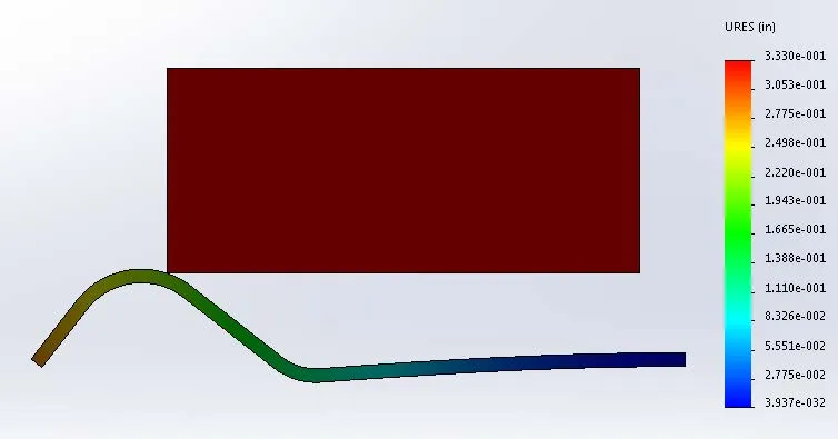
Figure 4: Displacement plot generated from the prescribed displacement
Ultimately, the purpose of this analysis was to find the application force required to displace the block and thus move the leaf spring. To do this, right mouse click on the ‘Results’ folder at the bottom of the study feature manager tree then select ‘List Result Force’ as shown in Figure 5.
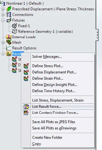
Figure 5: The menu system showing how to access ‘List Result Force’
Once in the ‘List Result Force,’ (shown in Figure 6) dialog select the edge on the block where the prescribed displacement fixture is applied and then select ‘Update’. The program will then report all of the X, Y, and Z force components applied through that fixture to give the desired displacement. In this case ~7.5 lbs.
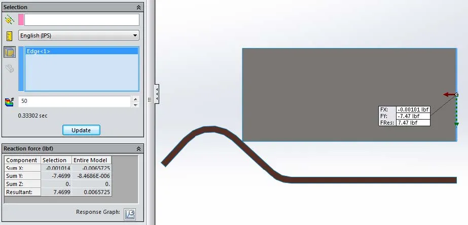
Figure 6: ‘List Result Force’ dialog and selections.
Keep Learning about SOLIDWORKS Simulation
SOLIDWORKS Simulation Tips: No Penetration Contact Set Setup
A Guide for Using Bearing Connectors in SOLIDWORKS Simulation
7 Steps to Perform a Fatigue Analysis in SOLIDWORKS Simulation
Frequency Study Plot with SOLIDWORKS Simulation
Introduction to Structural Analysis Using SOLIDWORKS Simulation Tools

About Ryan Dark
Ryan has been in the GoEngineer technical support team since February 2008 where he most notably provides support for all FEA and CFD software offered by SolidWorks. His most recent accolade is the title of Elite Application Engineer awarded by SolidWorks Corp.
Get our wide array of technical resources delivered right to your inbox.
Unsubscribe at any time.