Quickly Constrain a CAMWorks Toolpath Using Split Line
In this tutorial, you'll learn how to create and use a Split Line to quickly constrain a CAMWorks toolpath.
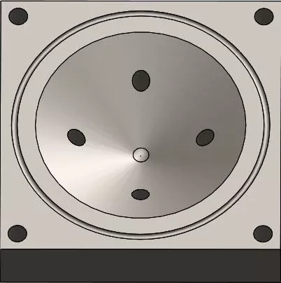
First, decide what the largest size ball end mill can be used without being too large of a diameter that it gouges the part.
You may want to hog out the extra material with a larger diameter and then change to a finish diameter, which you can do by simply creating a Split Line to stop the larger diameter end mill from gouging the part.
To create a Split Line, you need to first select a face, surface, or plane that you will create the sketch on, depending on where you need the Split Line to project.
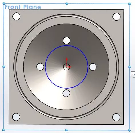
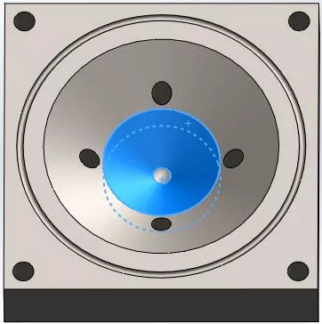
In this example, the Front Plane was used to create the sketch so that it will project downwards into the part. To keep a larger diameter ball end mill from gouging, it will need to be kept off of the bottom of the part where the Split Line will be projected.
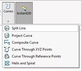
After the sketch is finished, select the Split Line feature located under Curves > Select Curves > Split Line.
Once Split Line is selected, choose the sketch and face(s) for it to be projected to.
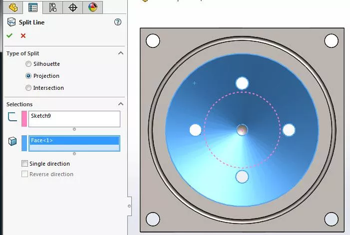
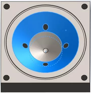
In this example, Sketch9 is selected which is the circle that was sketched on the Front Plane, and Face<1> is selected for the circle to be projected onto. We need to use Projection for this sketch to project onto the surface.
Notice that there are two selectable faces instead of one. We can easily program the upper surface to use a larger ball end mill and the lower surface to use a finish size end mill.
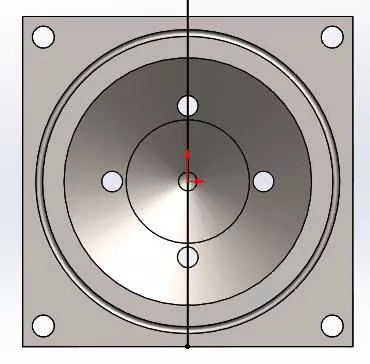
In this second example, Sillohuette will be used instead of Projection. Let's start with a single-line sketch on the face of the part.
Select the sketch line for the sketch and select the faces the line should project onto. When there are multiple faces that the sketch will overlap, select only the faces that you want the sketch projected onto. In this example, only two faces are selected.
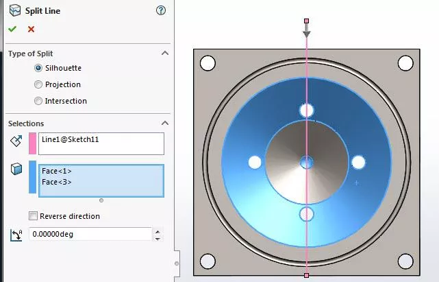
Here the line is only projected onto the two faces that we selected, skipping the non-selected face.
That wraps up this tutorial. To learn more about CAMWorks check out the articles listed below.
Learn More About CAMWorks
CAMWorks Air Segment Offset Explained
How to Set Up a Firewall Exception for CAMWorks Teksoft.exe
Suppressing Features in CAMWorks for Better Toolpaths
Creating a Coordinate System in CAMWorks

About Kregg Egan
Kregg is a CAMWorks and SOLIDWORKS specialist based in Salt Lake City, UT. Prior to joining GoEngineer, Kregg was a machinist for a medical research company. In that role, he was able to machine parts that were used to make life-saving medical devices which he found to be very rewarding. In his off-time, he enjoys riding motorcycles and tinkering on small projects.
Get our wide array of technical resources delivered right to your inbox.
Unsubscribe at any time.