Remodeling Airplane Wings with SOLIDWORKS
While moving some items stored at my parents' house, I came across a favorite childhood toy: an Army Men C-130 aircraft. It had been left in neglect, and in a storage space that caused the wings to warp. However, after looking at it, I realized I could recreate this vehicle in SOLIDWORKS to bring it back to life.
The first stage of this project was to model the wings. After removing the duct tape from the aircraft, I took multiple pictures to assist with the modeling.
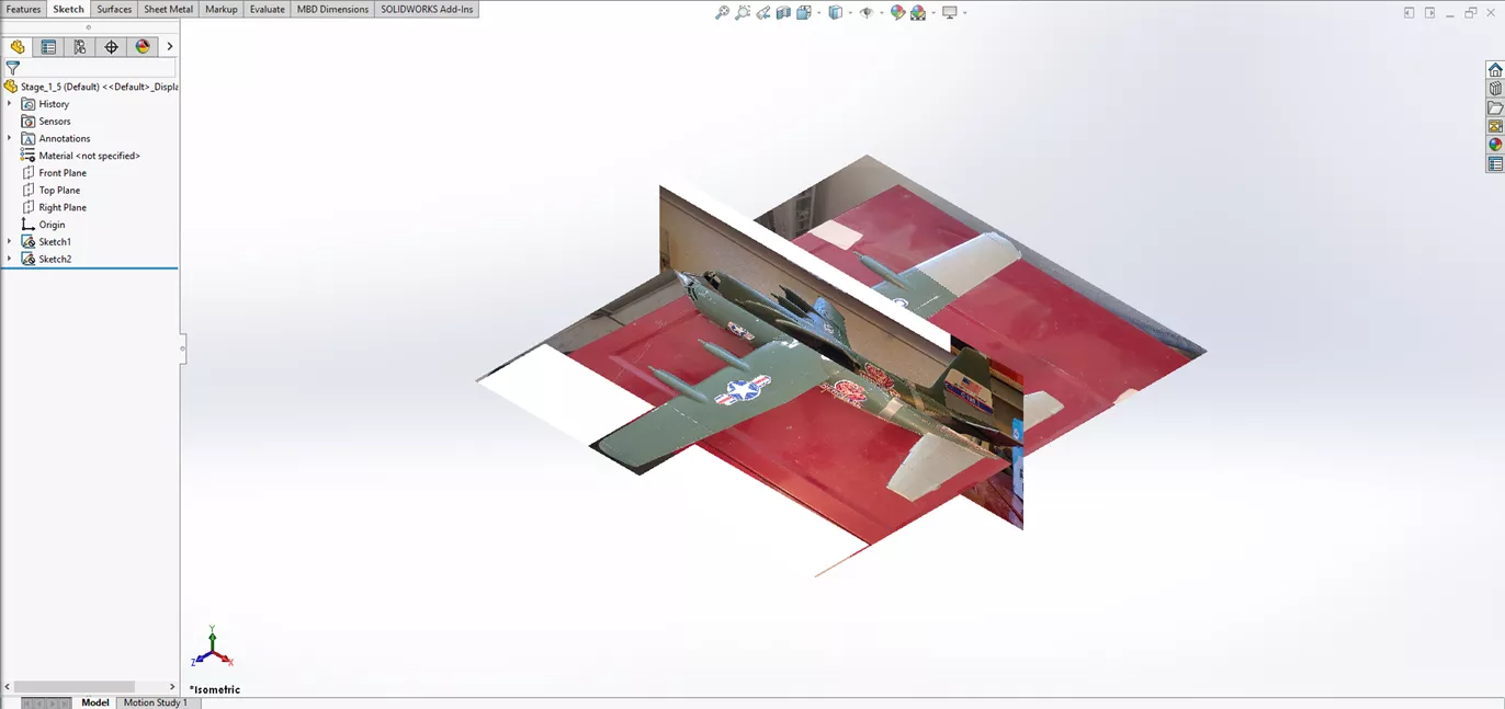
Next, I imported the sketch images into SOLIDWORKS using the Sketch Image tool. (The Autotrace add-in can also be used to help trace the profile.) Autotrace works best for higher-contrast images than these, so I'll forego using it this time.
Once I brought in the sketch images, aligned them, and adjusted their size I received the below results for the sketch images. I recommend right-clicking the sketch images and making them reference sketches to avoid accidental edits to the inserted images.
The next step was to create planes for the wing profiles. To do this, I created an initial plane 1 inch from the front plane. Then, I utilized the Linear Pattern tool to Pattern the new plane.
The patterning of reference geometry is a new feature in SOLIDWORKS 2025.
I noticed that the linear pattern resulted in a few too many planes in the early portion of the linear pattern. Going back into the tool, I can define those redundant planes as instances to skip.
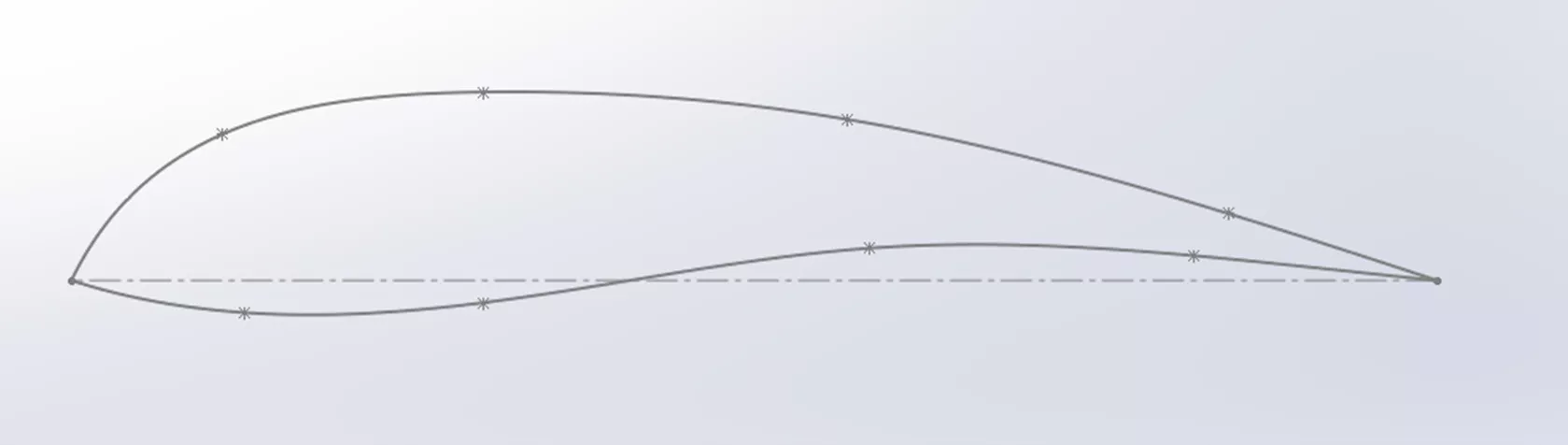
Now that I have the planes created, I can add the sketch profiles for the wings. I wanted to modify the profile of the wing and make it my own unique version of the craft.
With the initial sketch profile complete, the next step is to copy that sketch onto the other planes. Then, I will modify each of the copied profiles, by adjusting their size using the Scale Entities tool to create smaller profiles. Finally, I'll use the Move Entities tool to realign the left endpoints of each profile.
The final preparation item is to create the plane that the guide curve sketch will use, and then draw a guide curve along the front and back of the wings to prevent twisting in the loft.
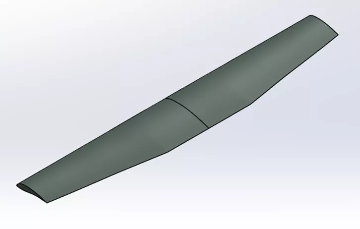
Now I'll create the loft feature, using the wing profile sketches and the guide curve. I recommend keeping the preview option active in the loft command, as this helps identify any twisting or undesired results while selecting the profiles.
With one wing now done, I can go ahead and mirror it to the other side to complete the wingspan and apply appearances to match the coloration of the plane.
That's a wrap for this article. The next series will include adding the main body, creating the propellers for the aircraft, and more.
Want to learn more? Check out more tips and tricks below. Additionally, join the GoEngineer Community to participate in the conversation, create forum posts, and answer questions from other SOLIDWORKS users.
Learn More About SOLIDWORKS
Changing SOLIDWORKS Temporary Graphics Colors
Creating Exploded Views in SOLIDWORKS with Selection Sets
How to Customize the SOLIDWORKS Hatch Pattern File
SOLIDWORKS Loft vs Boundary: Key Differences
![]()
About Blaze Johnson
Blaze Johnson is a Sr. SOLIDWORKS Support Engineer at GoEngineer.
Get our wide array of technical resources delivered right to your inbox.
Unsubscribe at any time.