Removing Combs from SOLIDWORKS Electrical PLCs
In this article, we discuss an issue with combs and channel grouping often seen while creating PLCs in SOLIDWORKS Electrical.
When creating a project within SOLIDWORKS Electrical, Programmable Logic Control is often used for automation. We can insert a PLC into a SOLIDWORKS Electrical project utilizing the PLC manager.
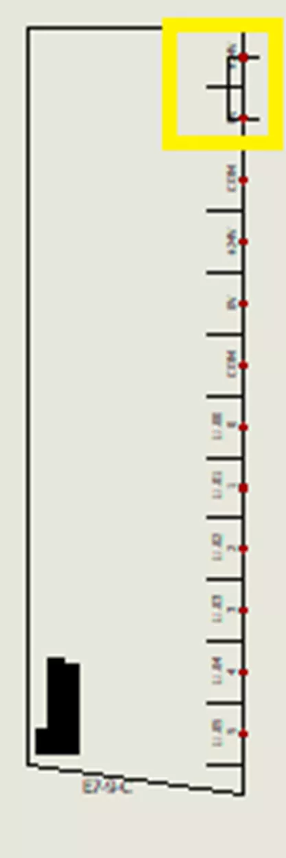
The PLC is located on the Project tab > PLCs. When adding PLCs to the project, select a manufacturer part to base this PLC. This is where the comb and channel grouping issues come into play.
Depending on the manufacturer, multiple channels may be grouped together. However, this can cause an unwanted comb or multiple unwanted combs to display on the PLC.
Luckily, there is a way to turn off combs in SOLIDWORKS Electrical, so you will never see them upon insertion of a PLC.
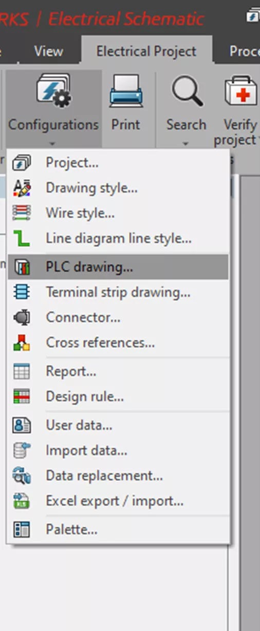
- Navigate to Electrical Project > Configuration > PLC drawing.
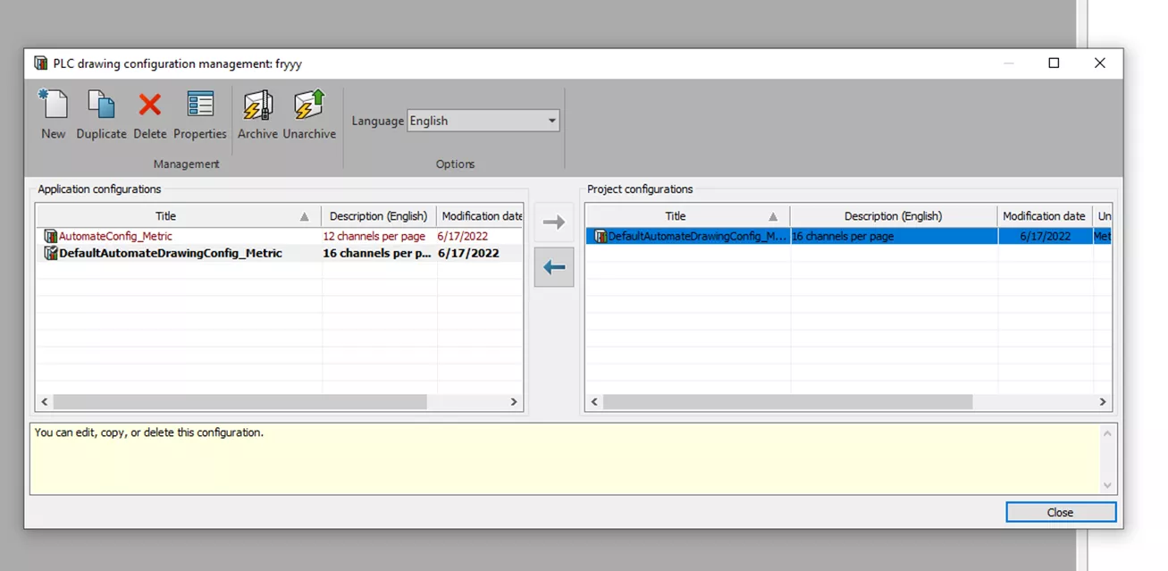
- Once in the PLC Drawing Configuration Management tool, select the configuration to modify, and select Properties.
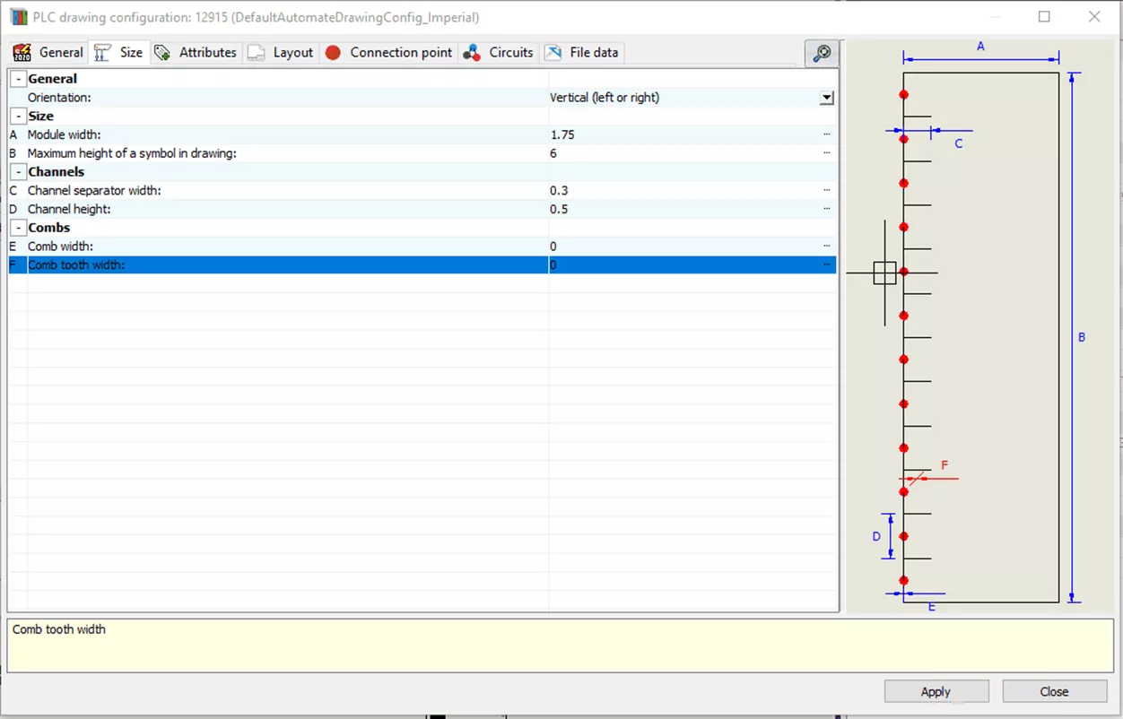
- In the secondary PLC Drawing Configuration Window that pops up, go to the Size tab and set both comb width and tooth width to 0. In the preview to the right, you can see there are no longer any combs inserted with the PLC.
Now, you are able to insert PLCs without the channel grouping being visually represented. Please note that if you make this change after inserting PLCs into a project, you must update the PLC symbols for this change to take effect.
I hope you found this article for removing combs from SOLIDWORKS Electrical PLCs helpful. Check out more tips and tricks below or visit our video library.
Editor's Note: This article was originally published in March 2020 and has been updated for accuracy and comprehensiveness.
Related Articles
SOLIDWORKS Electrical 2D: Changing the Automatic Root Value for Symbols
Component Marks in SOLIDWORKS Electrical
SOLIDWORKS Electrical 2024: Auto Balloons, Part Data, Ranges & More
How to Include External Data Files in a SOLIDWORKS Electrical Project
How to Create a SOLIDWORKS Rx in SOLIDWORKS, Electrical, and Composer
![]()
About GoEngineer
GoEngineer delivers software, technology, and expertise that enable companies to unlock design innovation and deliver better products faster. With more than 40 years of experience and tens of thousands of customers in high tech, medical, machine design, energy and other industries, GoEngineer provides best-in-class design solutions from SOLIDWORKS CAD, Stratasys 3D printing, Creaform & Artec 3D scanning, CAMWorks, PLM, and more
Get our wide array of technical resources delivered right to your inbox.
Unsubscribe at any time.