Smart Explode Lines in SOLIDWORKS Explained
What are SOLIDWORKS Smart Explode Lines?
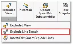
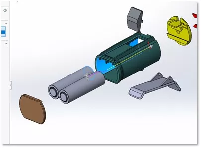
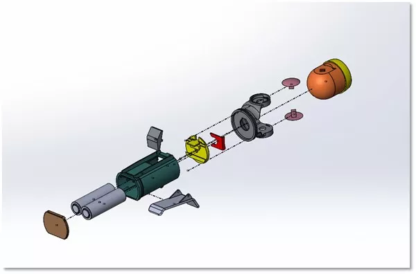
To understand what smart explode lines in SOLIDWORKS are, we first need to understand what an explode line is. An explode line is a route sketch line that helps to show the position a component came from before creating an explode in SOLIDWORKS. Explode lines can be a time-consuming task to implement. To apply explode lines, select the Explode Lines Sketch option under Exploded View, on the Assembly CommandManager.
You would then select edges, faces, or vertexes of the components you wish to create the explode lines for.
As I mentioned above, it is a time-consuming process, especially if you have a lot of components in your assembly. SOLIDWORKS has made this process very easy for us through automation. Smart Explode Lines is essentially an “easy” button for explode lines.
To access the tool, right-click on your exploded view and select Smart Explode Lines...
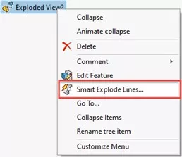
Once you select Smart Explode Lines, select the green checkmark, and you’re done.
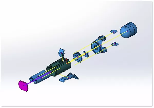
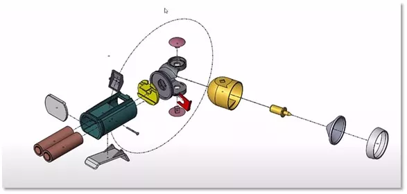
SOLIDWORKS will intelligently place the route lines for your exploded view.
Edit Smart Explode Lines in SOLIDWORKS
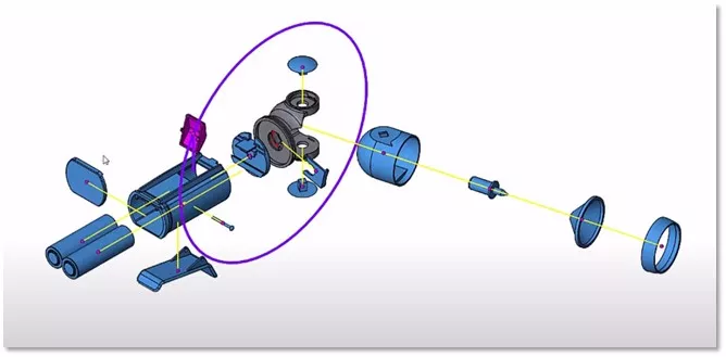
So, what do we do in the example that our resulting route lines are not how we want them to be? (Example below)
Under the Exploded View drop-down on the CommandManager, select Insert / Edit Smart Explode Lines.
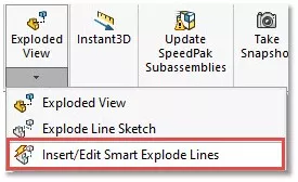
This option will bring us back into the PropertyManager where we can correct the problem.
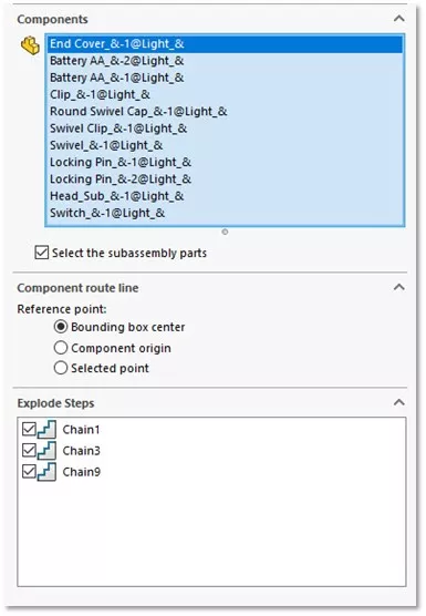
Quickly breaking down the PropertyManager, we have the Components area that shows which components are being selected in the explode line creation. The option to select the subassembly parts will allow you to draw route lines to parts in a subassembly.
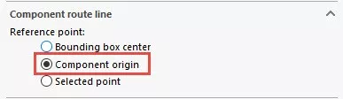
In this instance, we can correct the loop through the options of Reference Point. The three options for reference points are Bounding box center, Component origin, and Selected point.
- Bounding box center will create a route line relative to a bounding box of the component.
- Component origin will create a route line relative to the origin of the component.
- Selected point will create a route line from a point or vertex you select.
To go about correcting the issue in this example, you’d select the component that has generated the loop.
And then select Component origin.
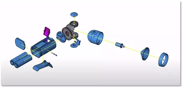
This will change the way the route is being generated towards the original position of the part.
This could also be done with Selected point by choosing one of the edges on the inside surface of the part and selecting a midpoint vertex. Once the green checkmark is selected, the edit will be completed.
Note: Smart explode lines will consider the order in which the assembly was exploded to create the explode lines. Try and create your exploded views in the order you would take them apart if it were a physical object.
I hope you found this SOLIDWORKS tutorial helpful. To learn more about SOLIDWORKS, check out more tips and tricks listed below.
More SOLIDWORKS Tutorials
Favorite SOLIDWORKS Tips from Tech Support
2 Ways to Reference a Cross-Section in SOLIDWORKS
Creating and Adding Weld Beads in SOLIDWORKS Models & Drawings
Record a Basic SOLIDWORKS Macro
![]()
About Nick Stanley
Nick Stanley is a SOLIDWORKS Technical Support Specialist at GoEngineer.
Get our wide array of technical resources delivered right to your inbox.
Unsubscribe at any time.