SOLIDWORKS Chain Component Pattern Tutorial
In this SOLIDWORKS tutorial, we explore an Assembly Feature for creating chains and other linked or looped mechanisms.
Creating a chain component pattern feature in SOLIDWORKS
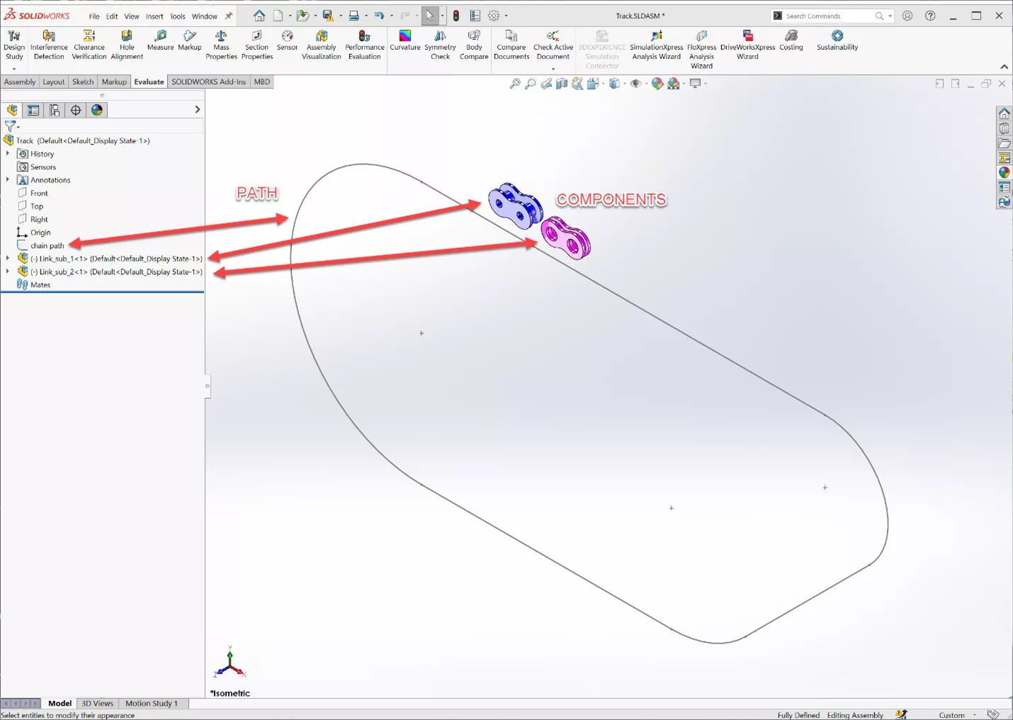
Before we can create this feature, the Assembly must contain a sketch of the path to be followed, and the components to be patterned.
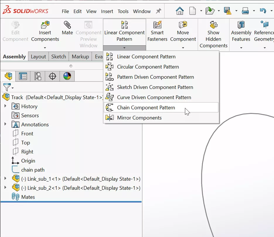
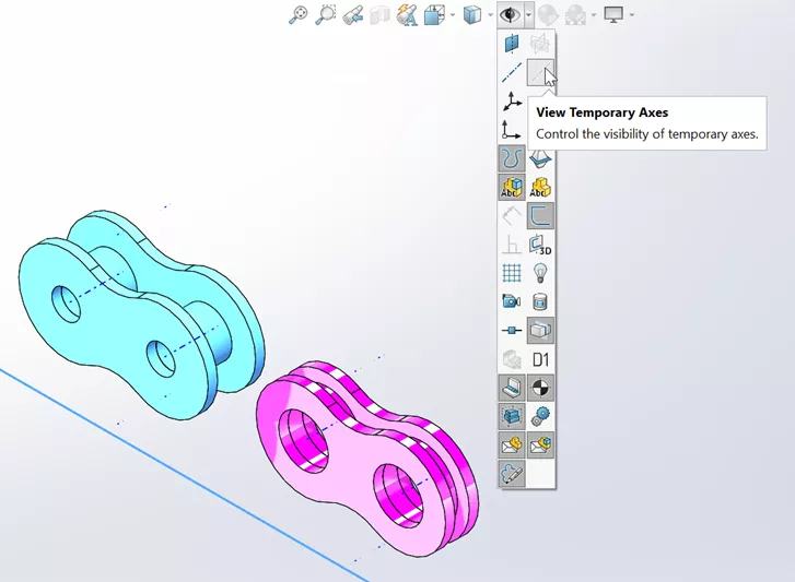
The Chain Component Pattern is accessed from the Linear Component Pattern pull-down menu in the Assembly tab (or use the Searchbar to locate it).
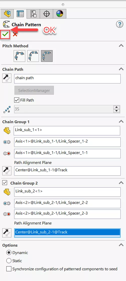
Its PropertyManager tab will be displayed as shown below.
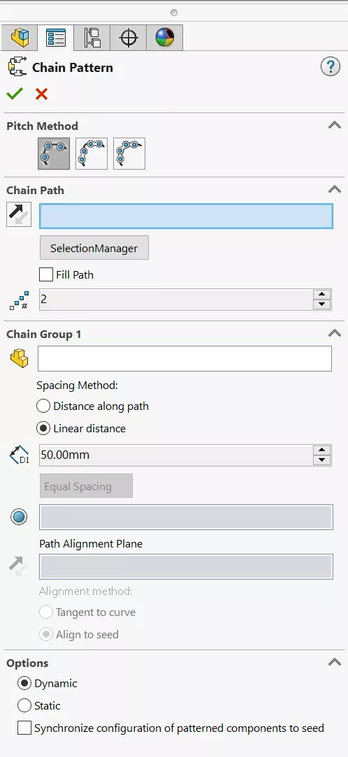
We will address each of these areas in order: Pitch Method, Chain Path, Chain Groups 1& 2 and Options.
Pitch Method
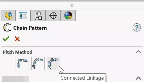
There are three options for the Pitch Method:
- Distance creates one group of patterned components spaced evenly apart. The components are linked to the path by a single piece of geometry.
- Distance Linkage creates one group of patterned components evenly spaced along the path. Each component is linked to the path with two pieces of geometry, so their orientations can change as they move along it.
- Connected Linkage creates a pattern using one or two groups of components evenly spaced that are linked to two pieces of geometry.
In this example, we will use Connected Linkage. This will allow us to select the two components that make up our chain assembly and allow for two pieces of geometry to constrain our components to the path.
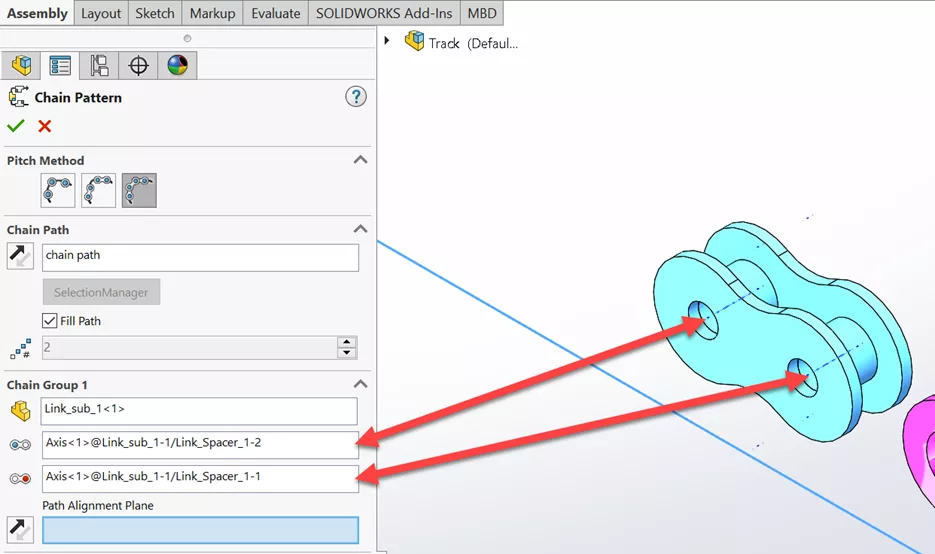
Chain Path
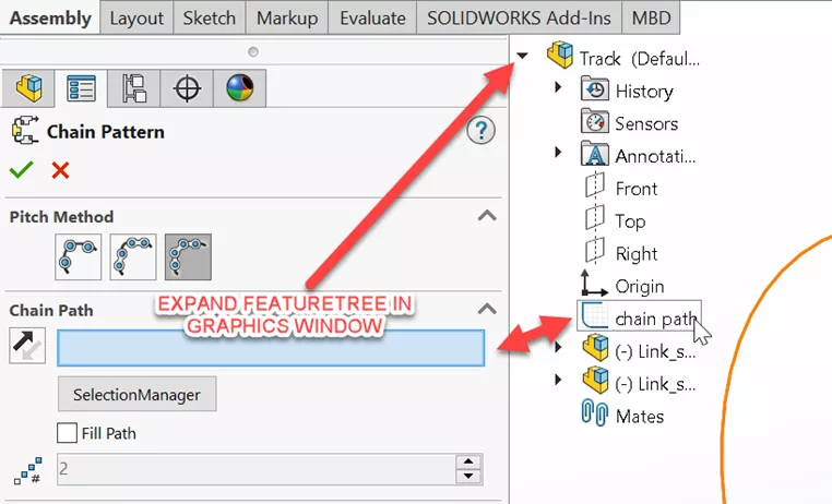
We can select the path we have sketched by expanding the FeatureManager Design Tree in the upper left-hand corner of the graphics window and clicking on the arrow next to the assembly.
Once we select the sketch (named "chain path" in this case) it will populate the chain path field in the window for us.
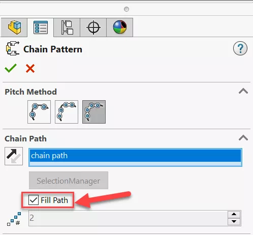
We are given the option to either Fill Path or define the number of instances. In this example, we will check the box next to Fill Path. Doing so will grey out the option to select number of instances.
Chain Groups
Let's look at our selection criteria for these two groups. The choices available will be identical for each, but the selection will differ.
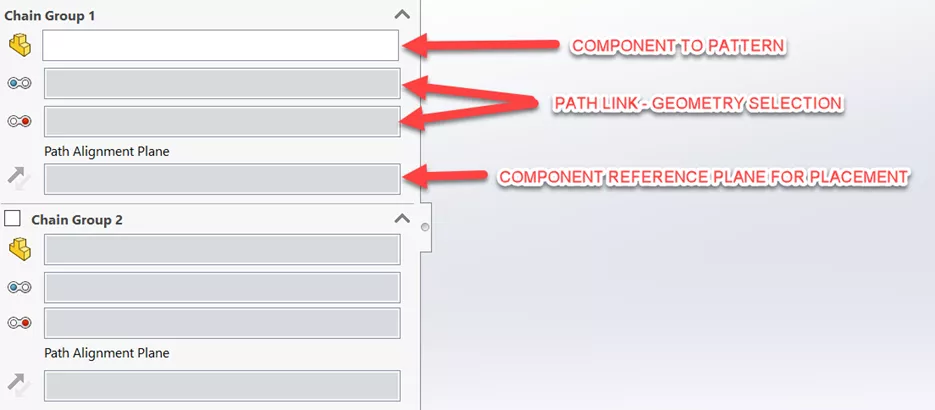
SOLIDWORKS uses the icons to the left of the selection boxes to indicate what we need to be selecting: the component we want to pattern, the features of the that component, and the reference plane in the component.
Chain Group 1
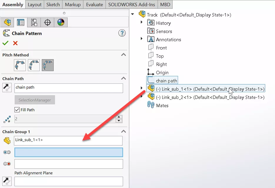
Expand the FeatureManager Design Tree in the graphics window to select the first component for Group 1.
When hovering your cursor over the selection boxes, the message indicates the selection options for this geometry, cylindrical face, circular edge, linear edge or reference axis. If we view temporary axes (from the heads-up display menu), we can easily select each axis for each of our geometry selections.
Now we need to align our component with a plane. We have a plane created in our component, which is centered on component geometry. We can expand our FeatureManager Design Tree in our graphics window to see and select this plane.
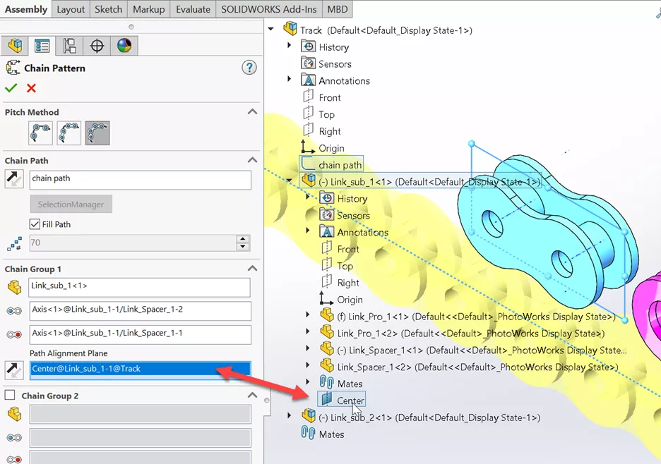
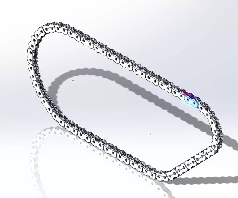
SOLIDWORKS can now start the preview of our chain assembly in the graphics window.
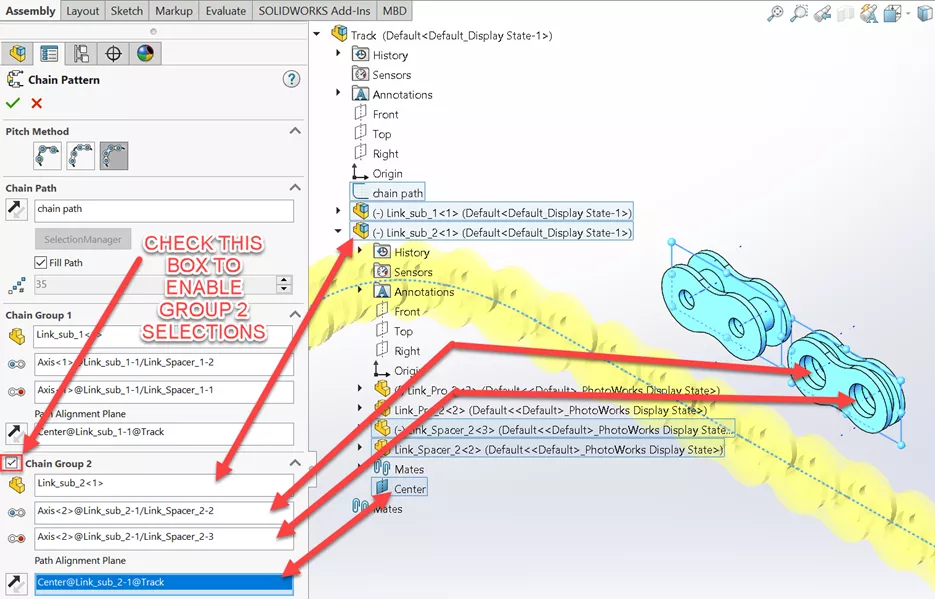
Chain Group 2
The method for selections will be the same for our next group except for the component, component geometry, and reference plane. To make these selections, we will first need to check the box next to Chain Group 2.
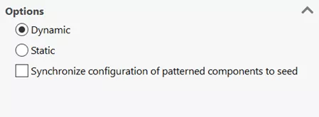
Options
- Dynamic allows movement of pattern about the sketch path.
- Static does not allow movement of the pattern about the path.
- Synchronize configuration of patterned components to seed prevents changes to the configuration of patterned instances. This option is available for component patterns and mirror components and applies to all configurations.
In this example, we will choose Dynamic and then test the movement of our chain pattern.
Click the green checkmark to accept our feature selections (OK).
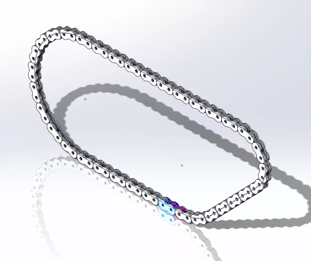
Using the LMB to select a component in the pattern and dragging that component, we can see the dynamic movement of our newly created chain pattern.
SOLIDWORKS chain component pattern demo
![]() To see the methods and instructions included in this article in action, check out our YouTube video.
To see the methods and instructions included in this article in action, check out our YouTube video.
More SOLIDWORKS Tutorials
Save Time! Customize Your SOLIDWORKS User Interface
SOLIDWORKS Drawings - Section Depth: Only Show What You Need!
SOLIDWORKS Sheet Metal Bend Calculations Explained
How to Create Design Library Features in SOLIDWORKS

About Matthew Kusz
Matthew Kusz is a Senior Technical Support Engineer at GoEngineer. When Matthew isn’t assisting customers with their engineering challenges, he spends his free time repairing antique watches/clocks, designing furniture, tending his aquariums and learning about bee keeping.
Get our wide array of technical resources delivered right to your inbox.
Unsubscribe at any time.