SOLIDWORKS Drawings - Section Depth: Only Show What You Need!
When creating drawings of an elaborate model, our views can suffer from unnecessary clutter. The challenge of CADD (Computer-Aided Drafting and Design) is to digitize the pencil. After all, a manual Drafter could draw any required detail, or in other cases, not draw unnecessary details that would confuse the drawing.
With a 3D model in SOLIDWORKS, generating drawing views is easy. In fact, too easy. As a result, many Drafters add extra pictorial and isometric views to their drawing because they are essentially ‘free’ because of the 3D model. While this can help to communicate the part or assembly, the manual Drafter rarely has the time necessary to generate these additional technical illustration views, and, in most cases, it is simply unnecessary.
Unquestionably, the 3D model gives us a lot of great information, however, it poses another problem: information overload.
For example, if you need to make a section view through a complex part or assembly, you will notice that important details can easily get buried in the extraneous information present in the model.
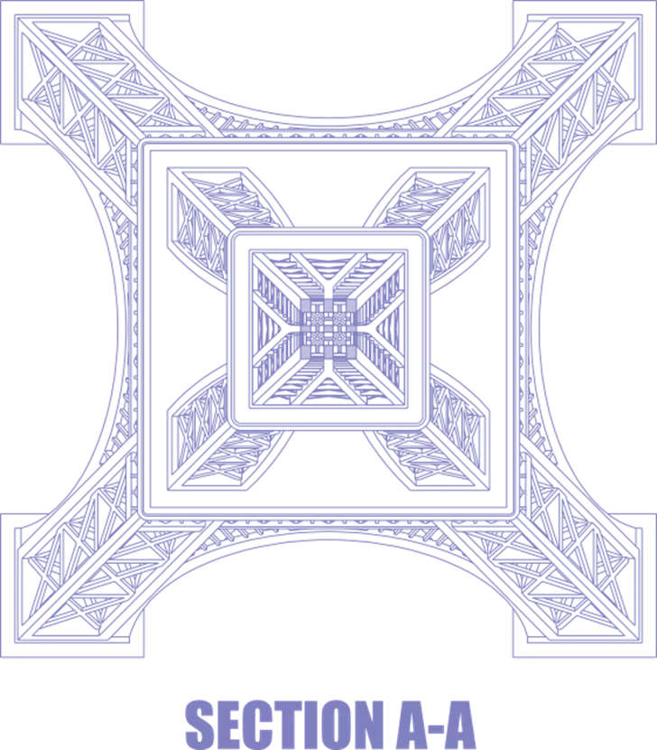
Take this excellent Eiffel Tower model created by Renato Nenadic and posted on GrabCAD. In this example, we take a section view of this tower from the top looking down.

The resulting section view on the drawing is perfectly complete. In fact, it shows all the cross members and other unnecessary details all the way down to the base, as it is all a part of the model. The primary reason for the section view is to show details of the weldment structural members at the top of the tower, but as shown here, it is difficult to see.
However, there are a few options to address this issue.
Section Depth Setting
One option is to use the Section Depth setting, which can be defined by a distance, point, edge, or line on the model as shown with the purple arrows and line below.
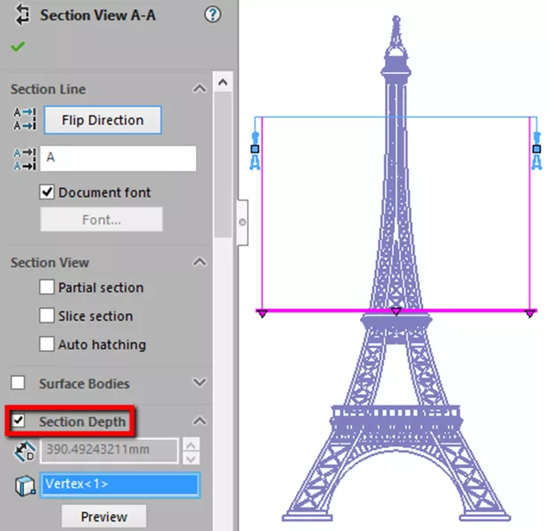
This setting tells SOLIDWORKS to discard all the model information that is beyond that selected point, edge, or distance. Select the Preview button to see the results before placing the view.
The result is a cleaner, trimmed-down section, allowing the Drafter more room on the drawing and allows for optional scaling of the section view for even more clarity.

Slice Section Setting
Another option is the Slice Section setting, which will only display the faces or surfaces of the structural members that are cut by the Section line.
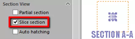
Thereby discarding the rest of the model. This is what the result of the slice section looks like, again, allowing the Drafter to scale the view accordingly.
More SOLIDWORKS Tutorials
Replacing a SOLIDWORKS Model in a Drawing View
Applying a New SOLIDWORKS Drawing Sheet Format to Existing & Future Drawings
Aligned Dimensions in SOLIDWORKS Drawings
Link SOLIDWORKS Drawing Balloon to Note

About Joseph Richter
Joseph is usually teaching in the Classroom instructing Engineers and Designers looking to get the most out of SOLIDWORKS. He is passionate about design and explains that it is not about what ‘he can do in SOLIDWORKS’, but rather what he can help others learn and accomplish in SOLIDWORKS. He has been serving the SOLIDWORKS community with excellence in Arizona since 2004.
Get our wide array of technical resources delivered right to your inbox.
Unsubscribe at any time.