SOLIDWORKS Sheet Metal Bend Calculations Explained
I have to assume that you are here because some aspect of your sheet metal design is causing your some heartache. Sheet metal designs can be knocked out in SOLIDWORKS in very short order. The tools available are robust and simple to use. However, depending on the precision with which you need your parts manufactured, their ease of use can make it easy to overlook a key factor in accurate parts - the flat pattern.
- Suggested Article >> SOLIDWORKS Sheet Metal Tutorial Using Flat Pattern & Sketch Bend
The flat pattern is calculated automatically by SOLIDWORKS using one of three methods: K-Factor, Bend Allowance, or Bend Deduction. Knowing the difference could make the difference between a part that fits, and one that doesn’t. This article aims to clear up the differences and help the designer make informed decisions about sheet metal part definition.
Differences between K-factor, Bend Allowance, and Bend Deduction
The decision to use one bend calculation over another is often made without any thought put into it and it can be confusing. To make more informed decisions, let’s first define our terms:
K-Factor
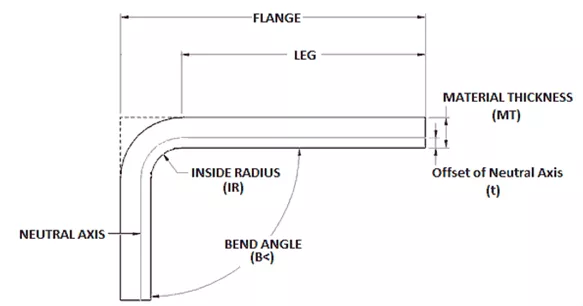
K-Factor is the ratio of the neutral axis to the material thickness.
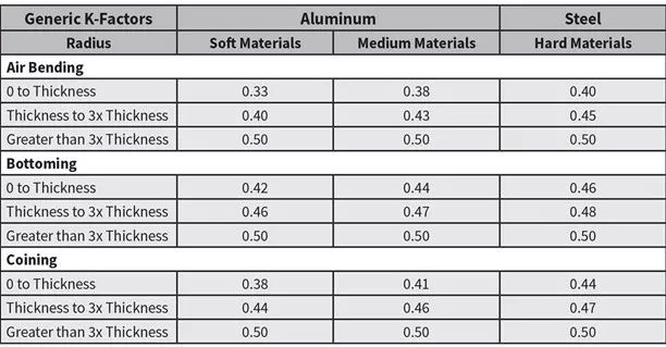
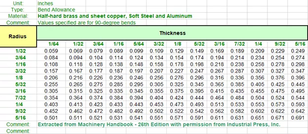
Many designers reference a chart like this or use test pieces to calculate the K-Factor for specific projects.
SOLIDWORKS defaults to calculating the flat pattern using the K-Factor. This is a decently conservative approach that will likely satisfy the majority of use cases. The table in the previous section shows some examples of how material types and manufacturing methods can influence the value for different bend radii.
Bend Allowance
Bend Allowance is the arc length of the bend as measured along the neutral axis of the material.
Bend Allowance is calculated as BA = π / 180 x ‘B<’ (IR + K x MT)
Bend Deduction
Bend Deduction is the difference between the sum of the flange lengths (from edge to the apex) and the initial flat length.
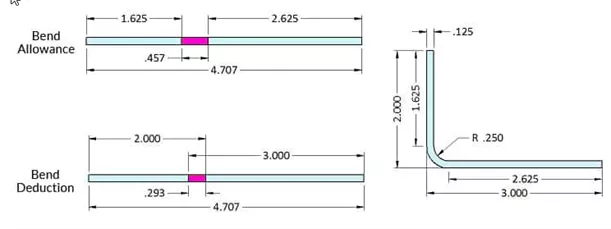
Do not be intimidated by the length of the formula for Bend Deduction. It is long because it solves for the Out Side Set Back (OSSB) as well as the Bend Allowance: BD = 2 x (tan (‘B<’ / 2) * (IR + MT)) - BA. If you already know the Out Side Set Back, it’s simply: BD = OSSB – BA
Now that you understand a bit about the math behind how flat patterns are calculated, let’s look at the tools available to you to automate all that information.
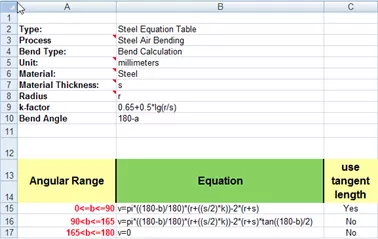
When choosing a Bend Allowance type, you can choose from K-Factor (the default method), Bend Allowance or Bend Deduction (values you’ve calculated for yourself or obtained empirical data for), Bend Calculation, Bend, or Gauge Tables.
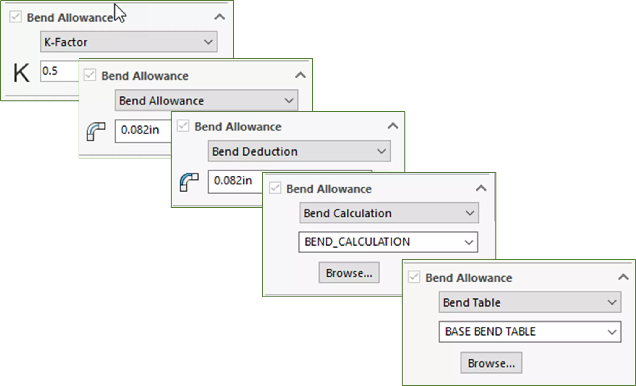
Each of the last three options point to Excel spreadsheets, which are responsible for generating the value that will be used for the Bend Allowance in your design. For the Bend Calculation option, the spreadsheet applies one of three equations – depending on the angle of the bend – to the sheet metal design.
With the Bend Table option, each of the available tables extracts the values for Bend Allowance – as it relates to the various radii and material thicknesses – from the Machinery Handbook.
If you are not manufacturing your parts in-house, it is recommended that you work with your vendors to determine proper bend allowance for your designs. Many vendors have developed custom tables that can be used with SOLIDWORKS to produce flat patterns that conform to the vendors’ capabilities and processes.
For more information on these tables, please refer to the help file articles linked below:
Want to Become an Expert?
Take the official SOLIDWORKS Sheet Metal training course from GoEngineer.
I hope you found this tutorial helpful. Learn more about SOLIDWORKS Sheet metal below.
More SOLIDWORKS Sheet Metal Tutorials
Using Sheet Metal Bodies in SOLIDWORKS Simulation
SOLIDWORKS Convert to Sheet Metal Command Explained
Creating Normal Cuts in Sheet Metal
SOLIDWORKS Sheet Metal Gusset Tool Tutorial

About Shaun Johnson
Shaun has been using and supporting SOLIDWORKS since 2000. After spending five years in a support role, he went on to develop products and solutions in industries ranging from consumer electronics to military aviation ground support equipment. Once again in a support role, Shaun enjoys leveraging this experience to help others realize their designs and transform pixels into parts. Whenever he can, Shaun fires up his coal forge and takes a more ‘hands on’ approach to creating parts from raw steel.
Get our wide array of technical resources delivered right to your inbox.
Unsubscribe at any time.