SOLIDWORKS Combine Feature Tutorial
The Combine feature in SOLIDWORKS is a great tool used most often in surface modeling as it allows you to take molds of created parts for mold operations. It is also useful when creating negative spaces for a part to fit into to show where an item might reside in an assembly.
How to use Combine Feature
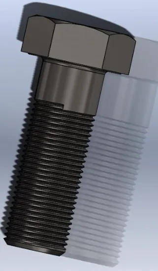
To combine, open your base component. In this example, we will use a basic screw.
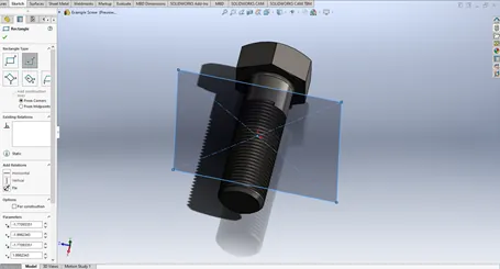
With the basic screw in the graphics area, we will create a sketch for our Combine feature to create a cut out of these threads. We will make a box using the center of the part to place a plane and sketch the box on.
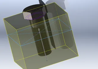
Once the sketch is created, Extrude the square in both directions to fully cover the threads up to the head of the screw.
Make sure to uncheck Merge Results as the default for SOLIDWORKS is to merge the bodies. By unselecting this, we ensure the parts are separated making the next command easier.
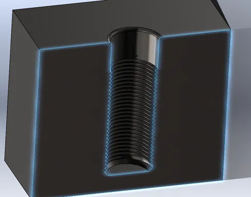
With the secondary body created, use the Combine tool to cut out the negative space in the cube.
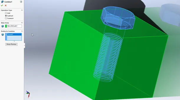
When we section the body, we now have a cutout of the threads after using the Combine feature.
Combine and Molds
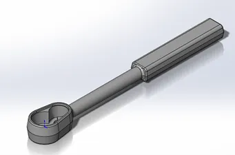
The Combine tool really shines when it’s being used to create molds. The process is much the same as above, but this will require covering the entire part.
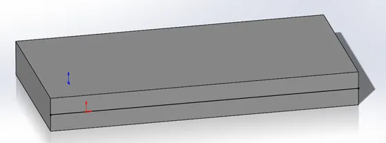
As with the previous Combine example, you will find the part and then create a body that covers the entire part. (shown below)
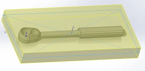
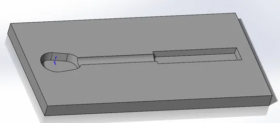
With the Body of the mold created around the part, and again, making sure to de-select Merge Results, we will work on the next step which is using the Combine feature to make a cavity for the part to be molded in.
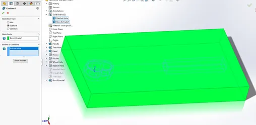
Below is the cavity, but we still need to do more.
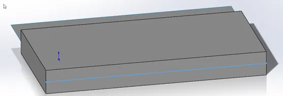
Next, we will need to create the parting line; we have the Core and the Cavity. To do this, we will need to create a sketch on the side of the mold
First, create a sketch on the left side of the mold.
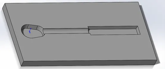
Under the Surfaces tab, use the Extrude Surface feature and expand the line through the part.
With that surface created, use the Cut with Surface option to cut the mold into both Cavity and Core. Once the cut is made, hide the surface we used to cut, and you can now save the file out as Cavity, with a quick edit of the direction in the Surface Cut, you can easily save out the other side as Core.
With these steps, you’ve created a simple Core and Cavity for a mold.
 We have a YouTube video that demonstrates this concept as well. View it here.
More SOLIDWORKS Tutorials
Working with Exploded Views in SOLIDWORKS
Inserting Model Dimensions into a SOLIDWORKS Drawing
Scaling a Part in SOLIDWORKS 2 Different Ways
SOLIDWORKS Path Mate Explained

About Krystal Petersen
Krystal Petersen is a SOLIDWORKS Technical Support Engineer based out of Auburn Hills, Michigan. Krystal studied Product Engineering at Oakland Community College and has earned her CSWA and CSWP Certifications. She joined the VAR channel in 2015 with DASI (now GoEngineer). Krystal is a huge fan of Star Wars and likes to spend her off time fishing and camping.
Get our wide array of technical resources delivered right to your inbox.
Unsubscribe at any time.