SOLIDWORKS Electrical Schematic: Displaying Alpha Numeric Rows & Columns
In this article, you will learn how to display Alpha Numeric Rows and Columns for the borders of a schematic in SOLIDWORKS Electrical Schematic.
First, let’s go over how title blocks are assigned.
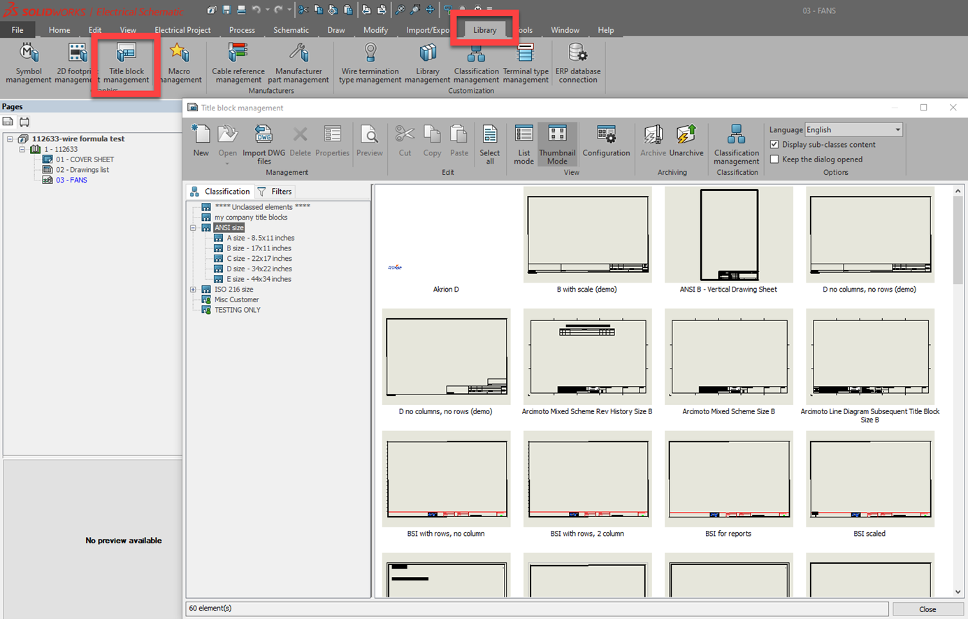
Go to the Library tab and then click on Title Block Management. Title blocks are grouped by classifications. You can choose a title block and edit it, or create a new one.
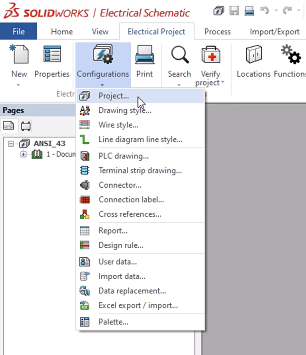
To assign a title block by default when new documents are added to the project, look at the Project settings. Click on Electrical Project, then Project Configuration.
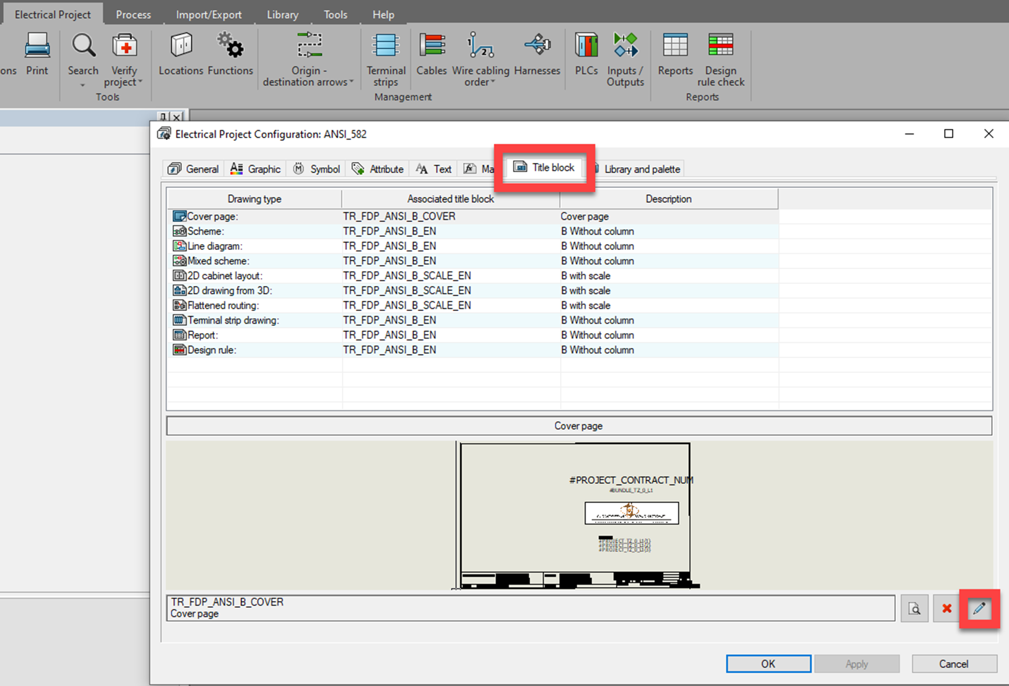
Click on the Title Block tab. Notice the document types on the left, along with the default title block associated with that document type. To change the default, click on the Search icon in the lower-right. This will open the Title Block Manager, where you can select the new default. Click Apply when you've made all your changes.
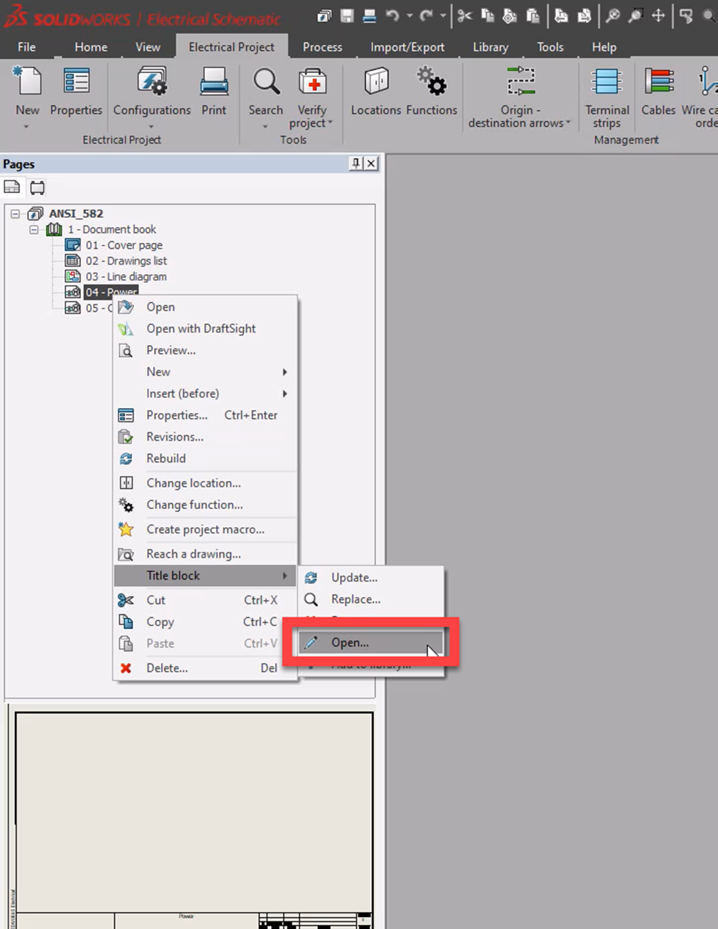
Another way to edit a title block is to right-click on the drawing in your project, choose the Title Block fly-out, and then Open.
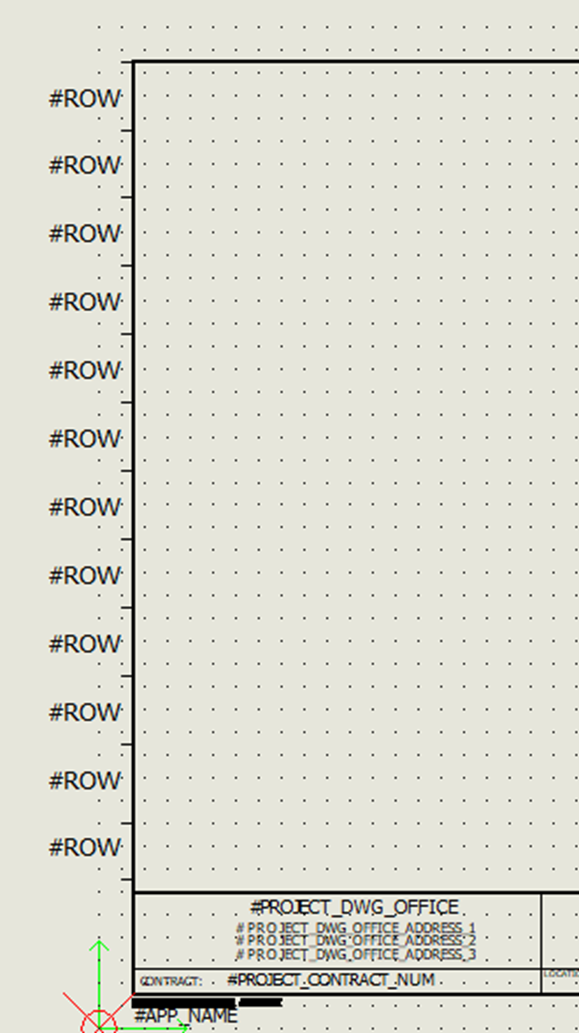
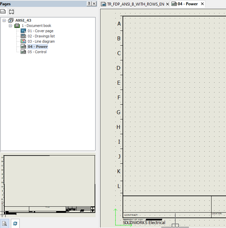
The title block rows and columns are populated where the attribute is on the title block drawing. The values that get populated where the attribute is, are defined by the formula in the Project Configuration. We will look at that later. First, ensure that the Row and Column attributes exist and are spaced according to your requirements.
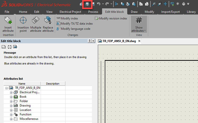
Once your attributes are in place on the title block, hit the save icon.
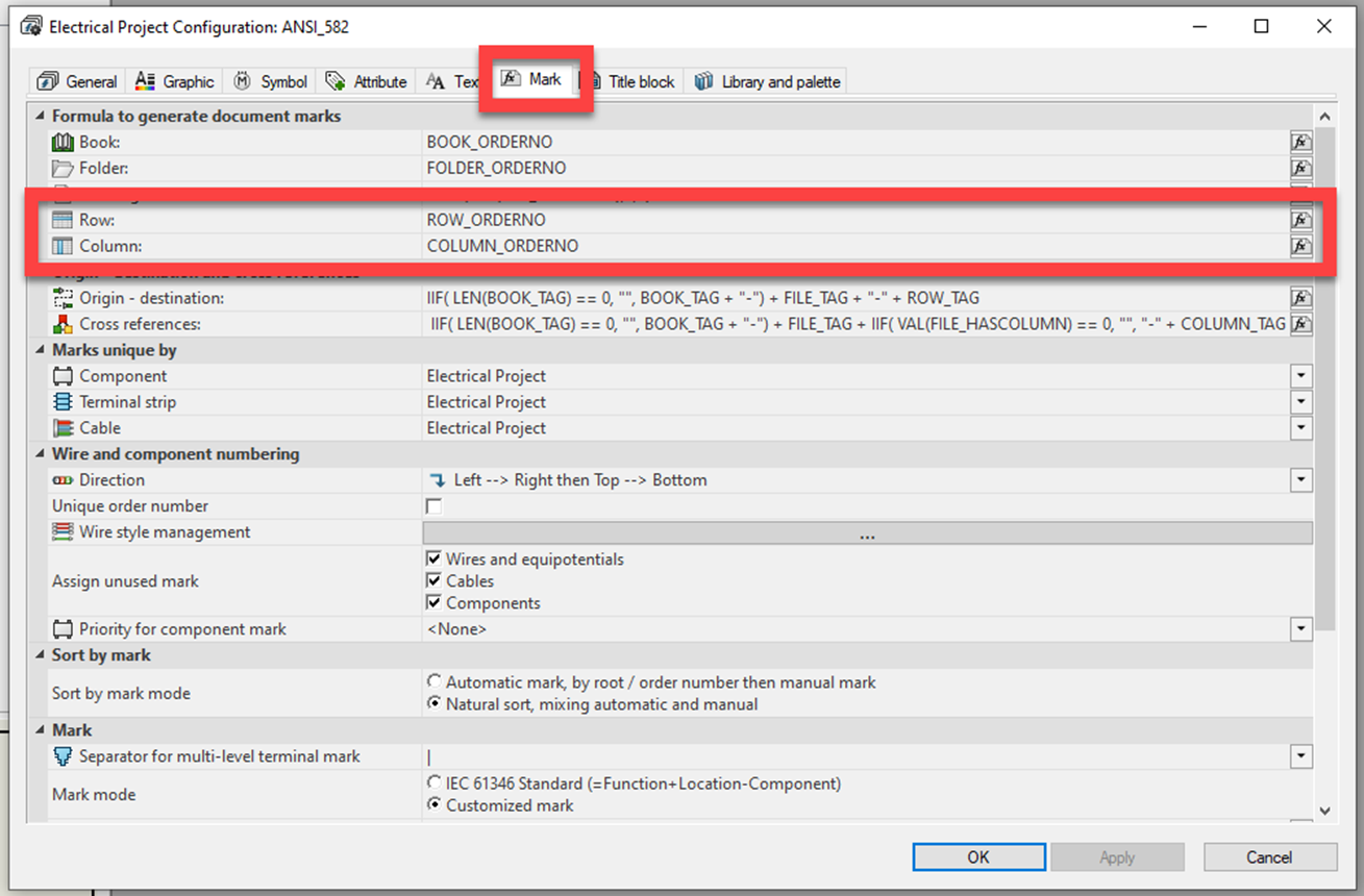
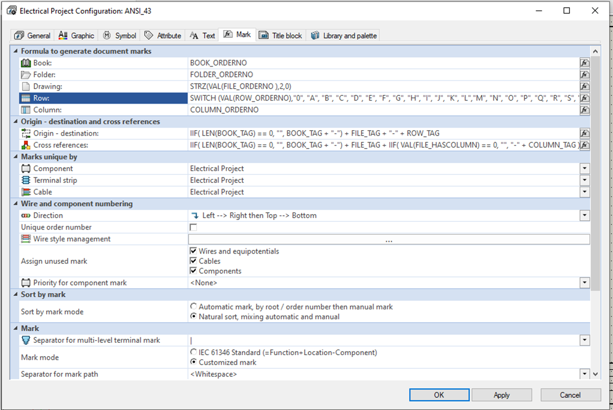
The next step is to define what will show for the Row and Columns in the Project Configuration. Click Electrical Project and then Project Configuration again. Click on the Mark tab. This is where the formulas are that define the Rows and Columns. Click on the Row or Column Formula icon.
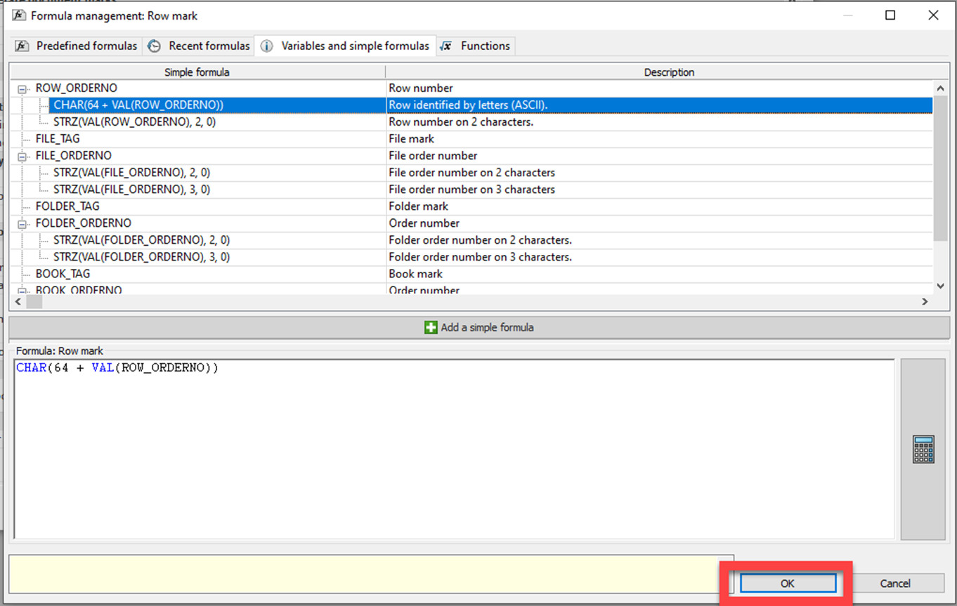
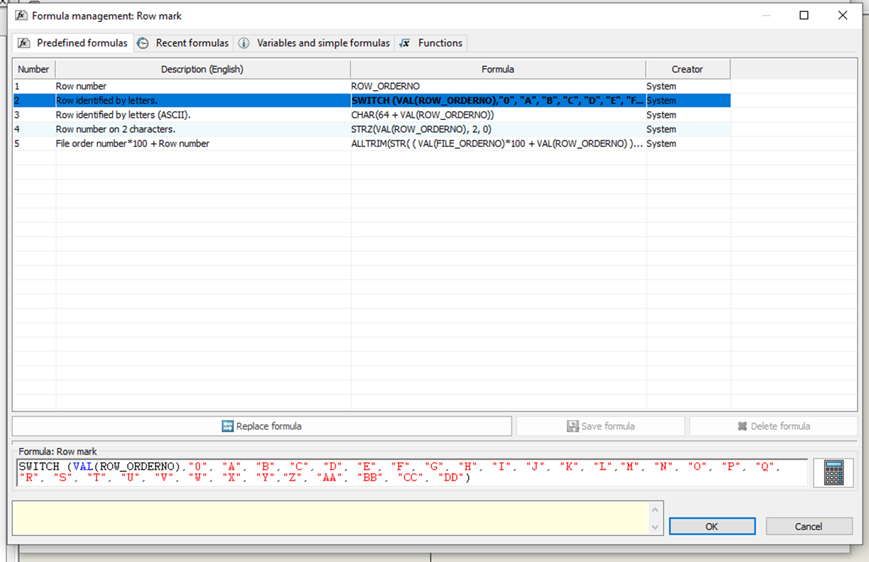
You'll want to change the formula to use letters. To do this, click on the Variable and simple formulas tab. Choose the formula for either Row or Column identified as Letters (ASCII). Click OK.
This alternative method allows you to call out whatever specific values you want. This example will use a formula that switches the value in the index to whatever is called out in quotations (in this case, letters). You can change any of the values in quotes to suit your specific needs if the predefined formulas do not work for you. I have the formula listed below that you can copy and paste:
SWITCH (VAL(ROW_ORDERNO),"0", "A", "B", "C", "D", "E", "F", "G", "H", "I", "J", "K", "L","M", "N", "O", "P", "Q", "R", "S", "T", "U", "V", "W", "X", "Y","Z", "AA", "BB", "CC", "DD")
Click Apply in the Project Configuration.
Note that the Books, Folders, and Drawing formulas can be changed with the same process if the formula manager is invoked from those options.
Want to learn more? Get the most out of your SOLIDWORKS Electrical software by visiting the links listed below. Additionally, join the GoEngineer Community to create forum posts, enter design contests, and answer questions from other SOLIDWORKS users.
Editor's Note: This article was originally published in November 2014 and has been updated for accuracy and comprehensiveness.
Related Articles
Adding PLC Drawing Configurations to SOLIDWORKS Electrical Projects
SOLIDWORKS Electrical Save Manufacturer Part Info in a Symbol
How to Change SOLIDWORKS Electrical User Data
Reusing Wires in SOLIDWORKS Electrical Across Multiple Projects
Import Symbols into SOLIDWORKS Electrical from Other Systems
![]()
About David Foster
David Foster is a Senior Electrical Specialist at GoEngineer.
Get our wide array of technical resources delivered right to your inbox.
Unsubscribe at any time.