Adding PLC Drawing Configurations to SOLIDWORKS Electrical Projects
When working in SOLIDWORKS Electrical, you will often need Programmable Logic Control (PLC) for automation. This guide explains the process for adding PLC Drawing configurations to Electrical projects.
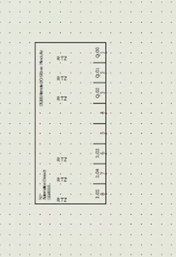
PLC Drawings
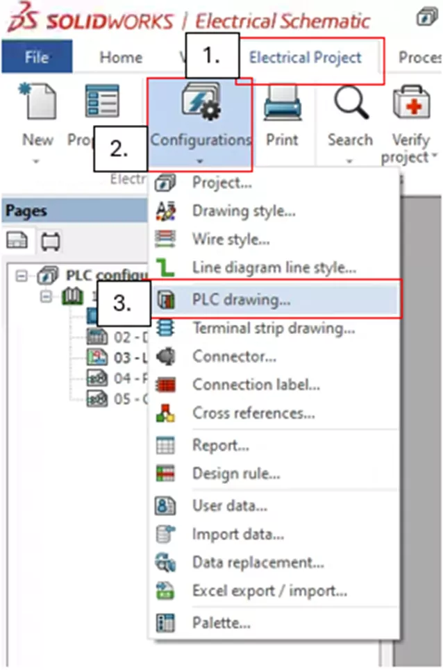
First, navigate to the PLC Configuration Manager and open your project. Once open, navigate to the Electrical Project tab, select the dropdown menu under Configurations, and select PLC drawing…
This will open the PLC drawing Configuration Manager, which provides several options.
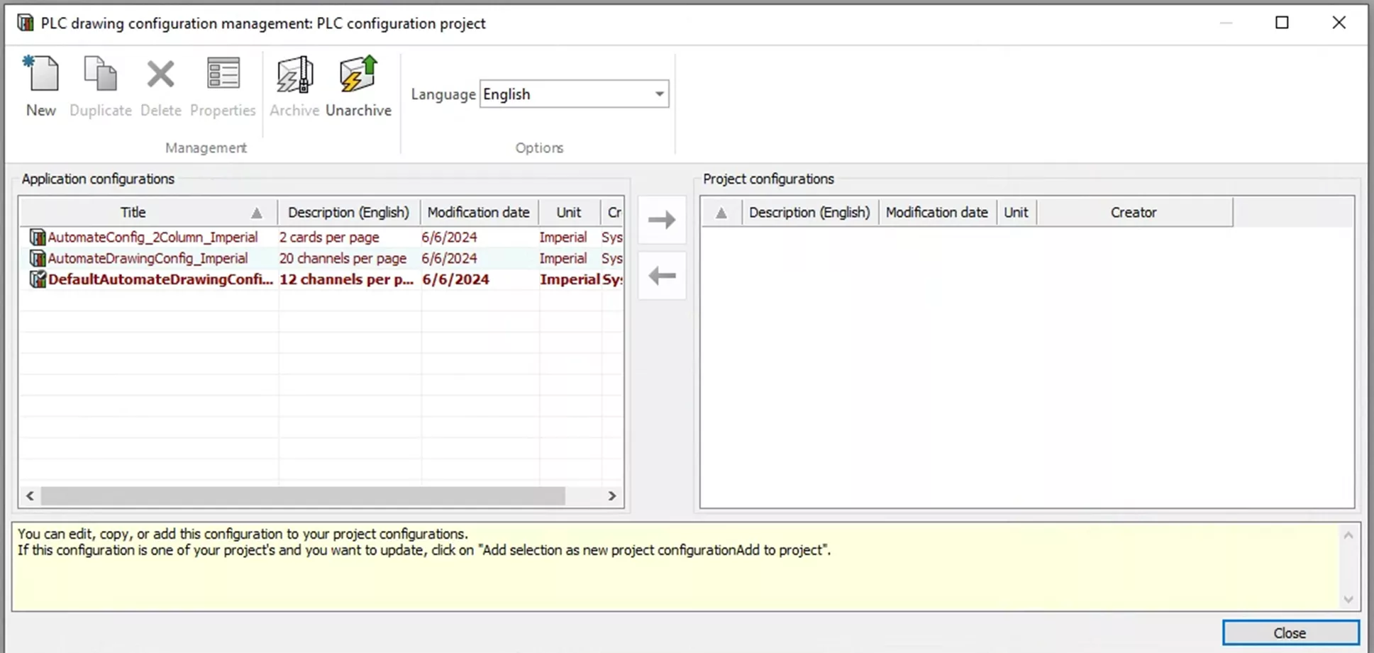
You are given a couple of options to add Application Configurations to your Project Configurations. The first is New, which allows you to manually create Application Configurations from scratch.
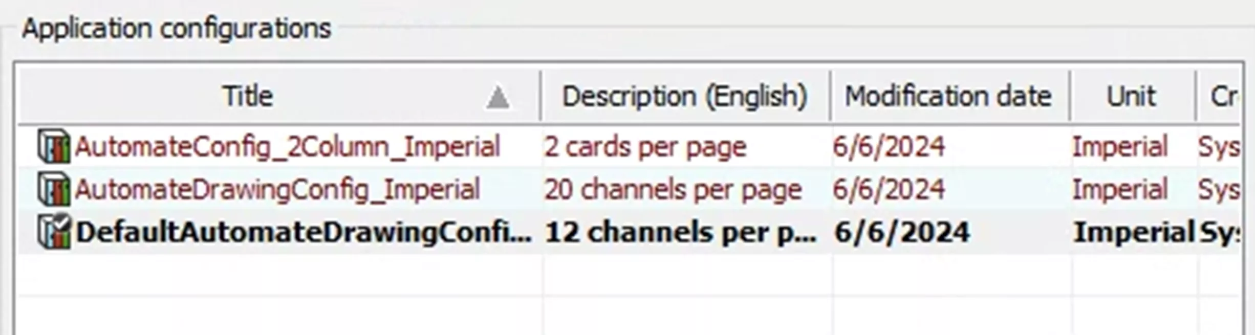
The second option is pre-generated default Application Configurations. They are ready to go and can be added to the Project Configurations.
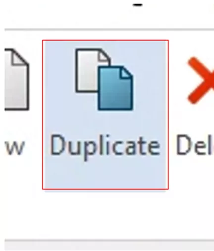
With these configurations, you can also duplicate and modify them to fit your needs.
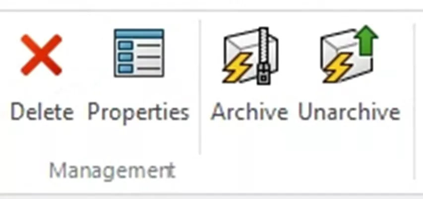
The PLC Configuration Manager offers other useful tools. When an Application Configuration is selected, you have the option to Delete this configuration. Selecting Properties will open a menu where you can modify several settings and parameters for this PLC Configuration. You can also Archive this PLC Configuration, which will create a .tewzip file. This file can be moved and unarchived in a different project/system.
New Application Configurations and Editing Existing Configurations
Now that you're familiar with the PLC Configuration Manager, let's choose to create a new configuration or edit an existing configuration.
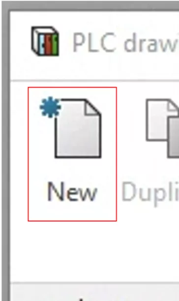
To create a new configuration, select the New option. This will automatically open the properties for this new configuration.
The first page that appears once the properties are open is the General tab. Here, you can name your configuration and add a description (in a variety of languages).
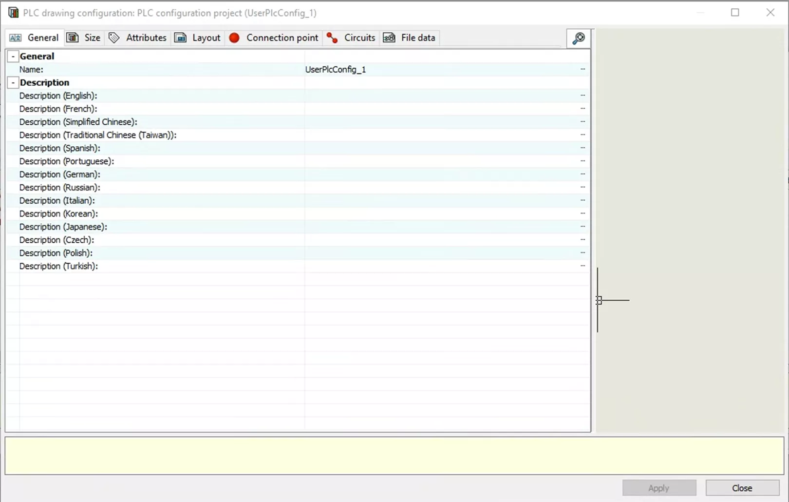
For this example, I will leave the default name and will not add a description.
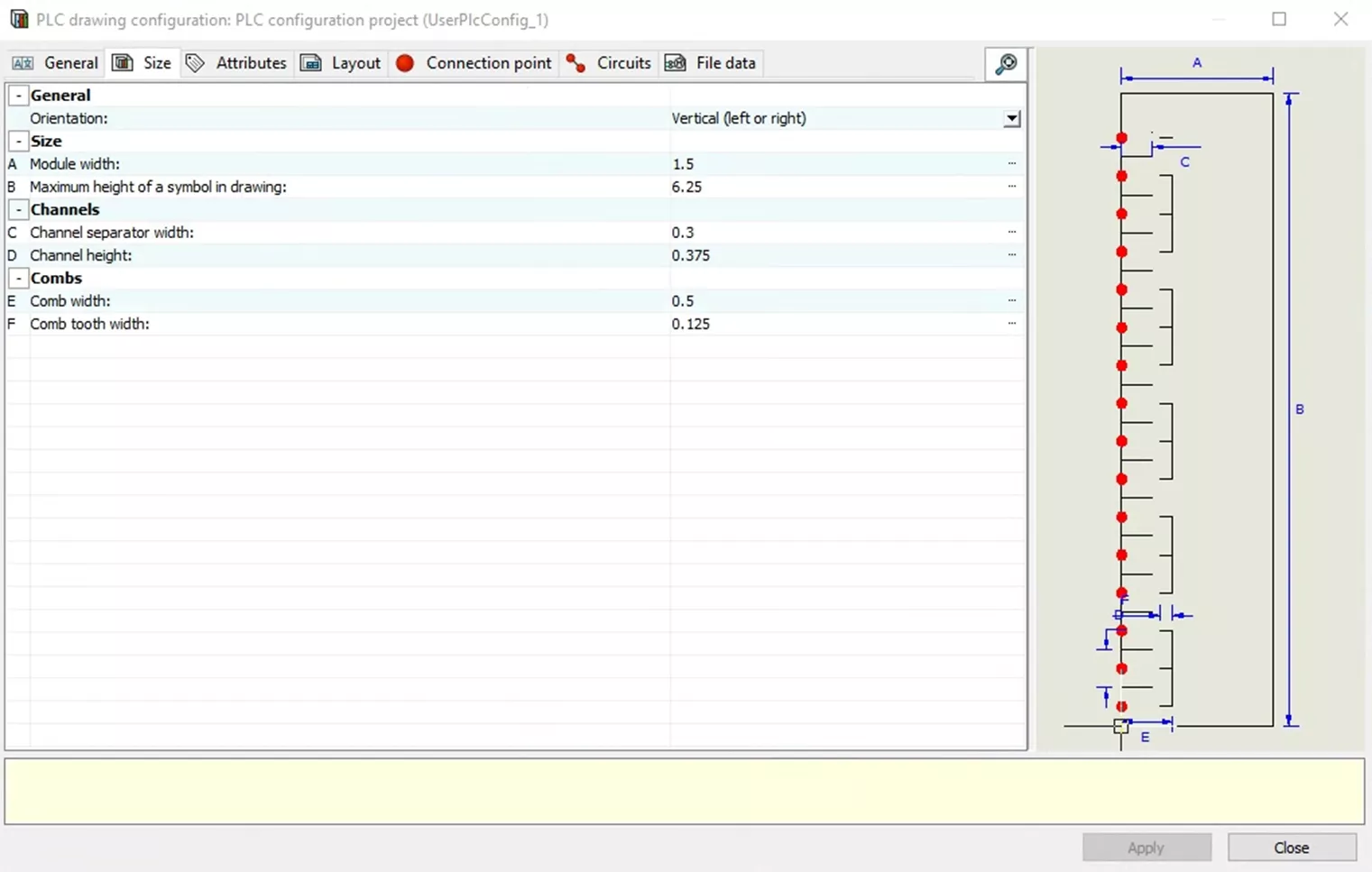
Next is the Size tab, which includes several attributes you can customize to match your needs. These include:
- Orientation
- Module width
- Maximum height of a symbol in a drawing
- Channel separator width
- Channel height
- Comb width
- Comb tooth width
Each is labeled with a letter from A-F, respectively. The letters then match to an example PLC and its dimensions, shown on the right-hand side. For this example, I will leave the default values.
In the Attributes tab, you can select your symbols, where they will be located, and what attributes they will display. Currently, there are only coordinates for the symbols and another example with dimensions.
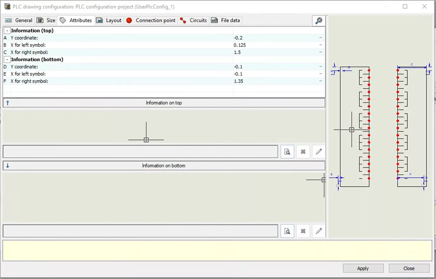
Two sections are labeled Information on Top and Information on Bottom. These allow you to add the symbols you want and then see a preview of what this will look like. Select the Search icon to add a symbol.
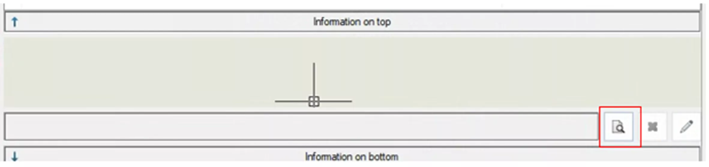
When you select the search icon, a list of PLC Symbols will appear that you can select from. Click on the symbol you want to use and hit Select. For this example, I will select Analog PLC Input Information(top).
After selecting a symbol, the previews update. The Information sections show your symbol, and the example on the right shows these symbols in place.
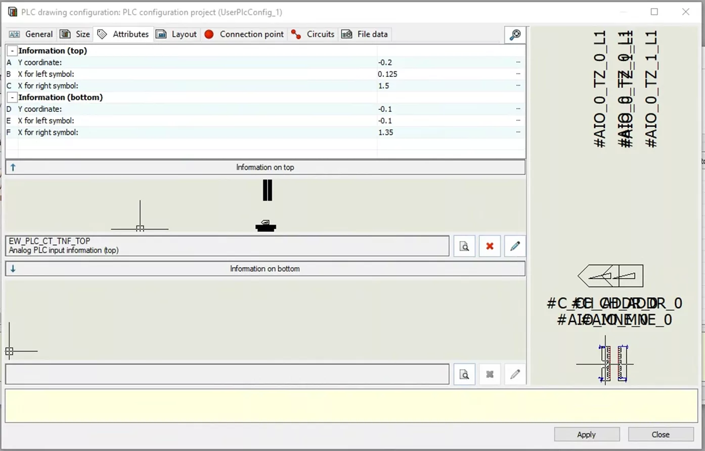
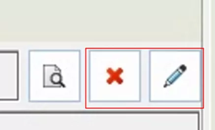
Adding a symbol will display additional options in the Information sections. The red X allows you to delete the symbol (whether added in error or to replace the current symbol). The pencil button opens the symbol and allows you to edit it just like you would any other symbol.
For this example, I will repeat this process for the information on bottom and continue to the next tab.
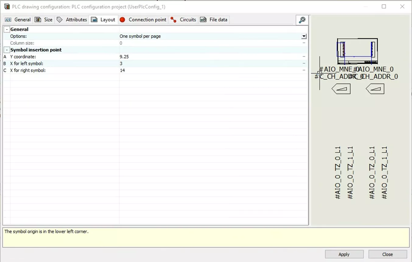
The Layout tab (like the previous tabs) offers a set of dimensions and shows an example of how this will look. The dimension I am setting this time defines where my PLC will sit on the drawing sheet.
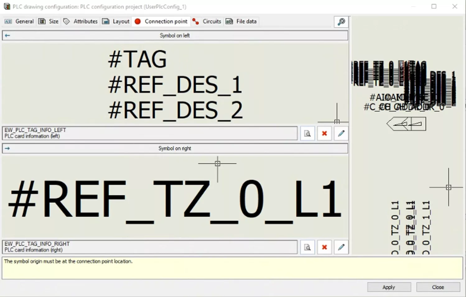
The Connection point tab allows you to select symbols for the left or right side. Much like the Attribute tab, you can select a symbol that can then be customized to show the desired attributes. Here, I will select the symbols PLC card information left and right side. Notice there is no geometry shown, but there are attributes.
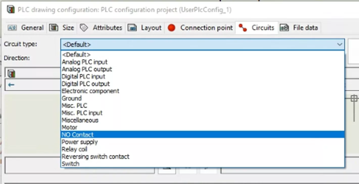
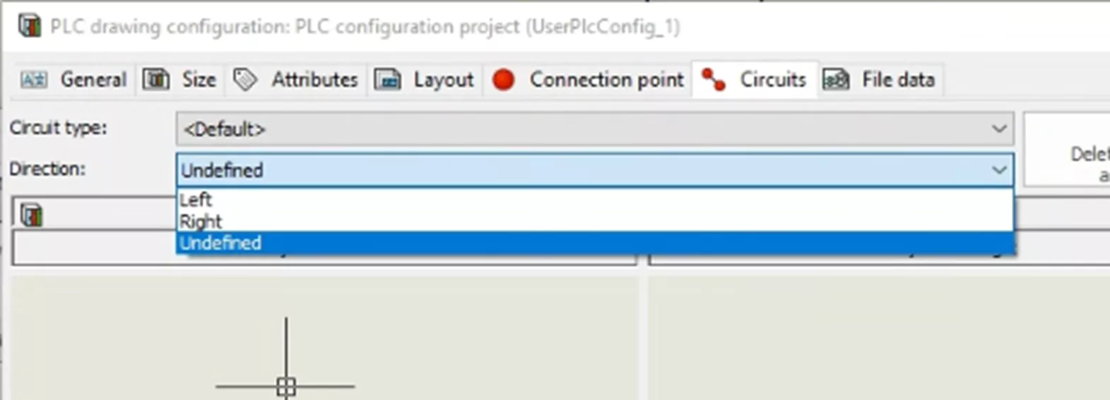
The Circuits tab is similar to the Connection Points and Attributes tabs, as it involves selecting symbols. However, this tab includes additional information that needs to be defined. At the top of the menu, you'll find the Circuit type dropdown menu, where you can select the type of circuit you are working with.
Another dropdown list allows you to define the direction of the circuits.
The next sections are the PLC Channel Pattern Symbols and Macro Connected to Channels. For the PLC Channel Pattern Symbols, you can select symbols that represent the inside of the module for insertion at the top or bottom of your drawings.
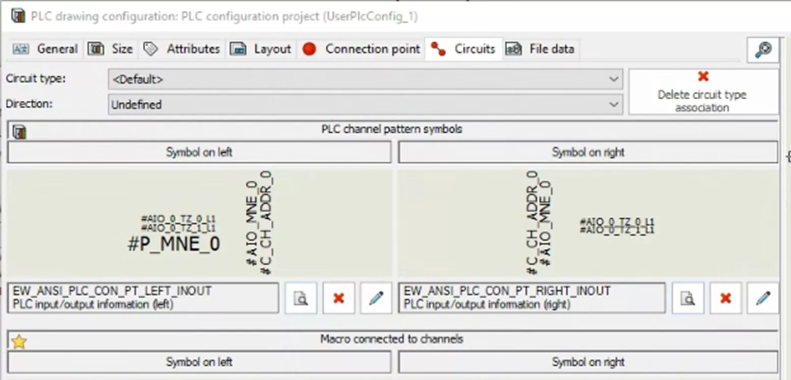
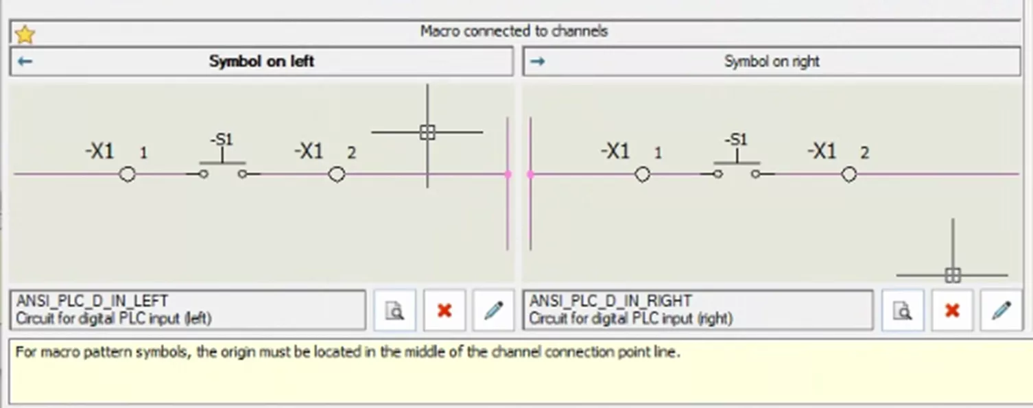
For the Macro Connected to Channels, you can select how your connection points appear in the drawing. This time, instead of symbols, you are selecting from Circuit Macros. The Macros represent the visual look of the connection points and do not focus on Attributes.
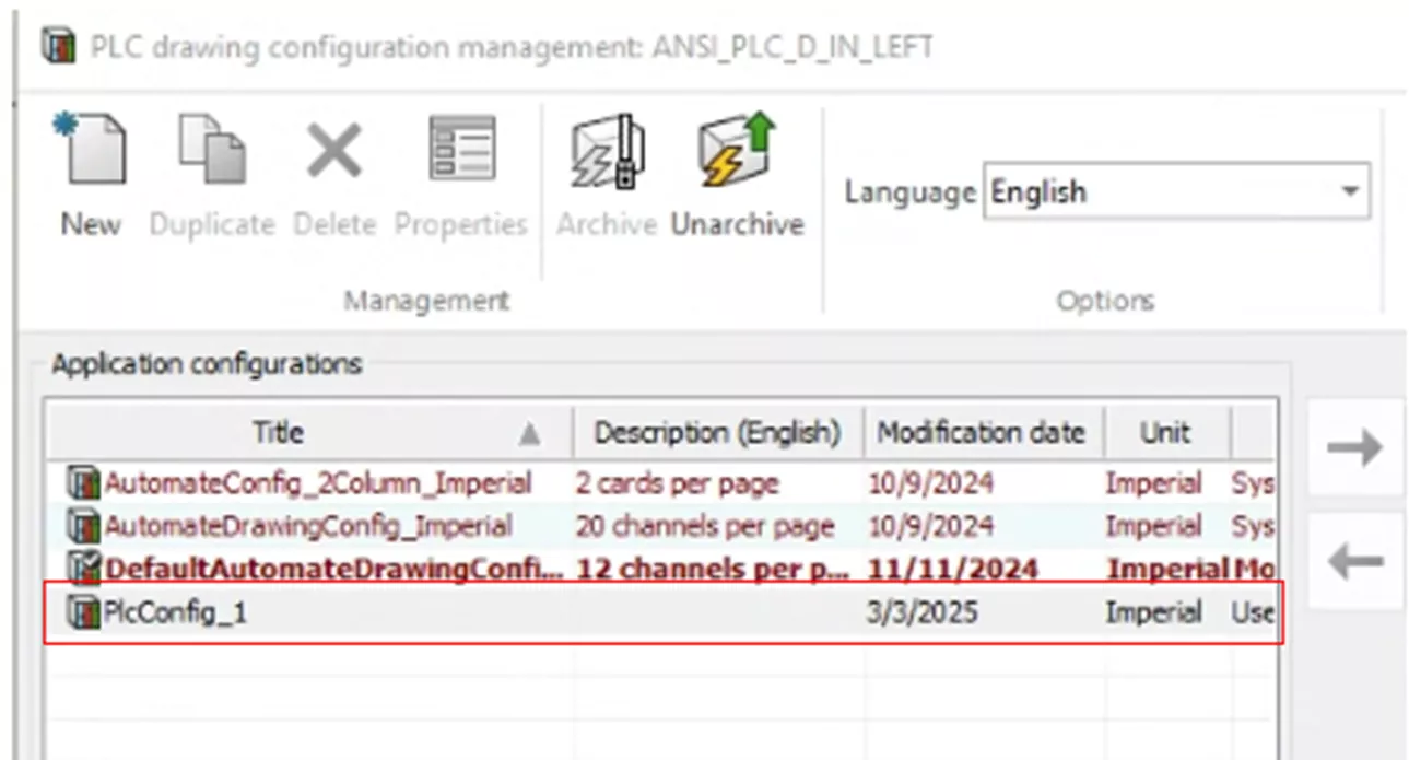
In the File Data tab, you can add further descriptions, user data, and translatable data as needed. When you've finished configuring the PLC Configuration, select Apply and then Close. Back in the PLC drawing configuration management menu, your new PLC configuration will appear in the list of Application configurations.
If you don't want to create a new PLC Configuration, you can modify an existing one. To do so, select an existing configuration and then Properties. This will open the same menu we just went through and allow you to edit the existing information to match your needs. If you want to use the existing PLC but keep the original intact, select Duplicate to create a copy. Select Properties and modify as needed.
Adding PLC to a Drawing
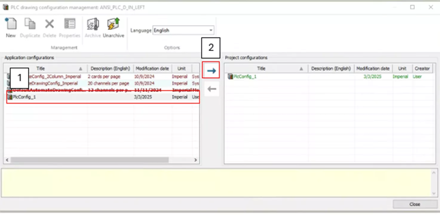
Once a PLC configuration is set up, it can be added to a drawing. While still in the PLC drawing configuration management menu, select your custom PLC and click the right arrow button to add the Application PLC to your Project PLC list. Select Close.
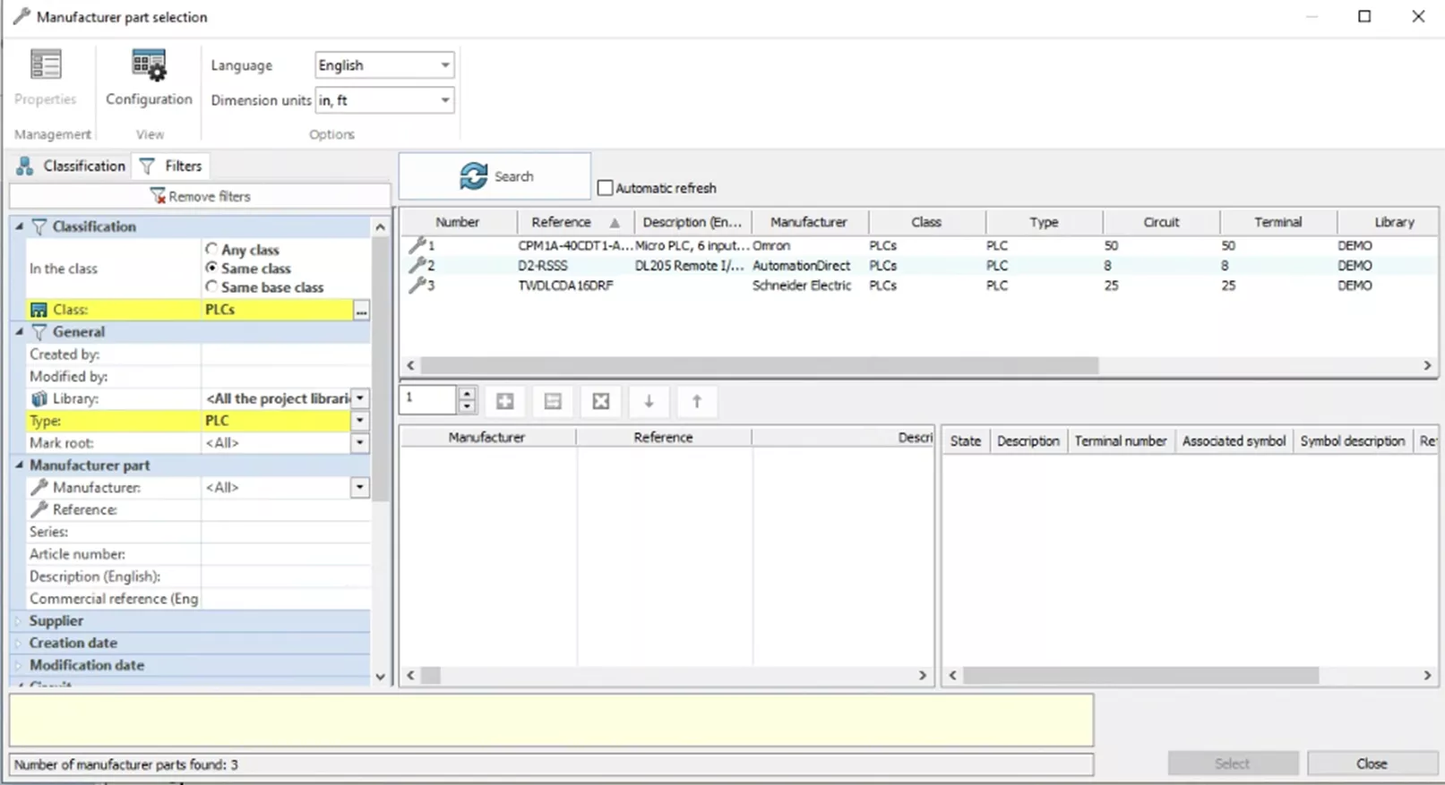
Next, right-click on Document Book, select New, and then Scheme. From here, you can rename your drawing. Insert the PLC by going to the Schematic tab and selecting Insert PLC. This will bring up the Manufacturer Part Selection menu, where (using filters), you can search for the PLC you need.
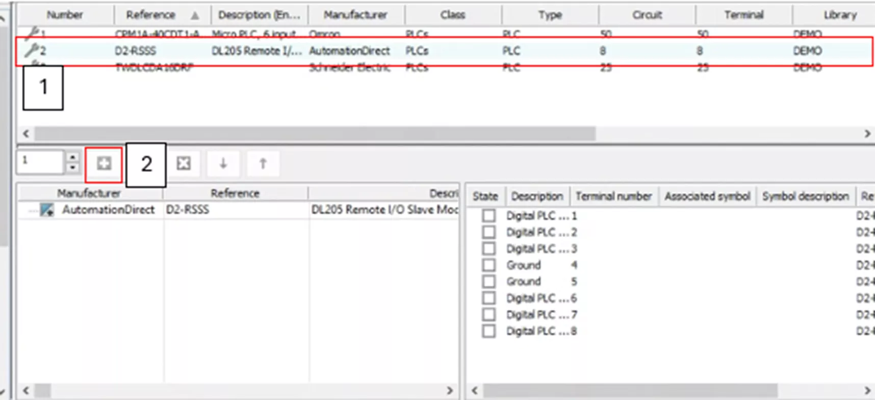
Once found, highlight your PLC and hit the green plus button to add it. Then hit Select.
In the Component Properties, you can further configure the PLC as needed. There are two tabs: Mark and Data and Manufacturer Part and Circuits.
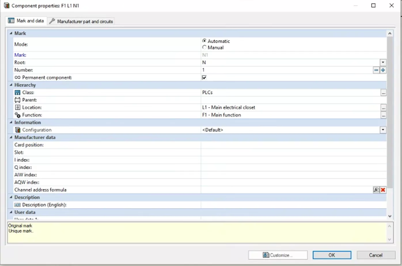
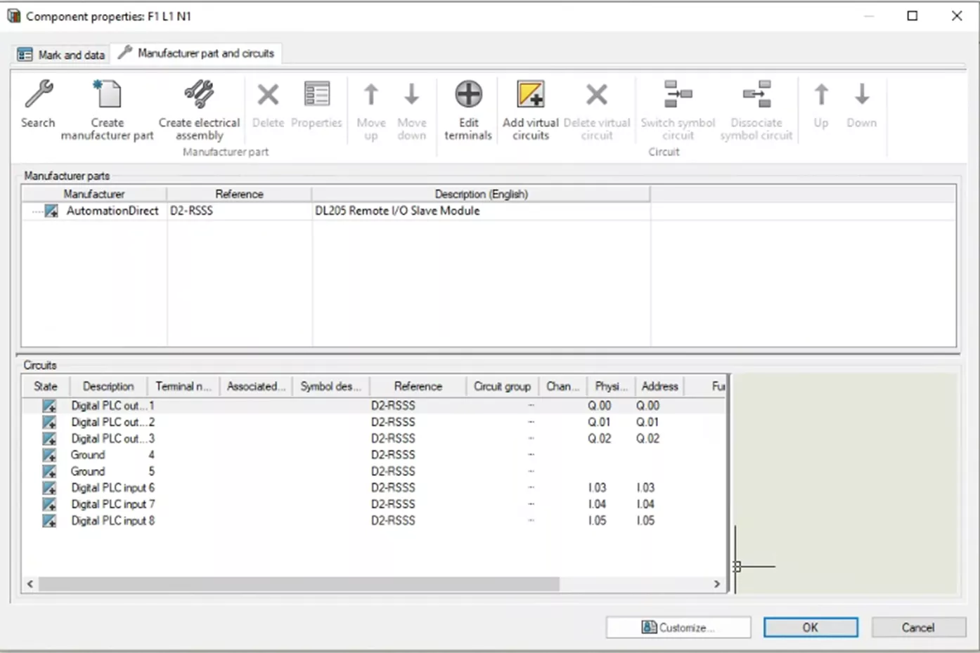
For this example, I will not change anything and will just hit OK.
Once exiting the Component Properties, enter Dynamic PLC Insertion. On the left-hand side are menu options to control which PLC you insert. In the drawing, you can see a PLC attached to the cursor for placement.
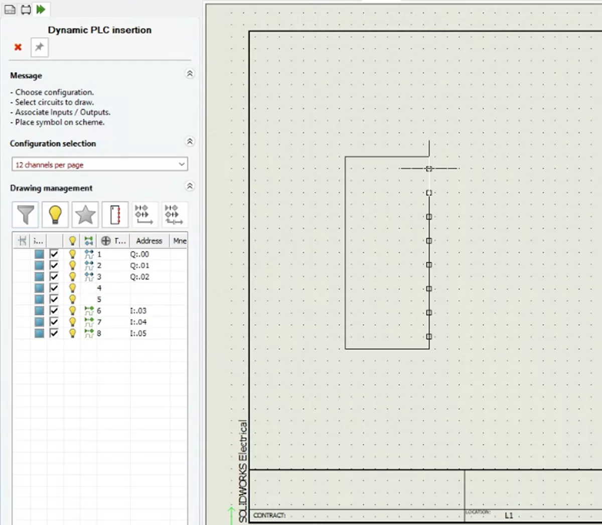
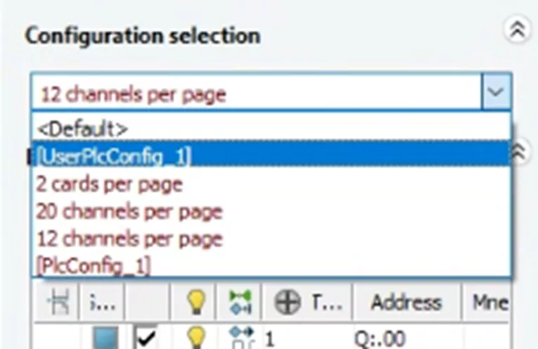
Before you place our PLC, change the Configuration from the Configuration Selection menu dropdown. This dropdown shows all PLC configurations, both Application and Project PLCs. Select your Project PLC, which is highlighted green.
Below the Configuration Selection are several tools that can be used to control what is inserted with our PLC. From left to right:
- Filter List: Shows only circuits not yet inserted
- Hide Unused Channels: Hide unused channels (circuits with no associated input/output)
- Insert Macros: Insert associated macros
- Change Directions: Change channel direction
- Associate I/O: Associate inputs/outputs with PLC channels
- Dissociate I/O: Dissociate inputs/outputs with PLC channels
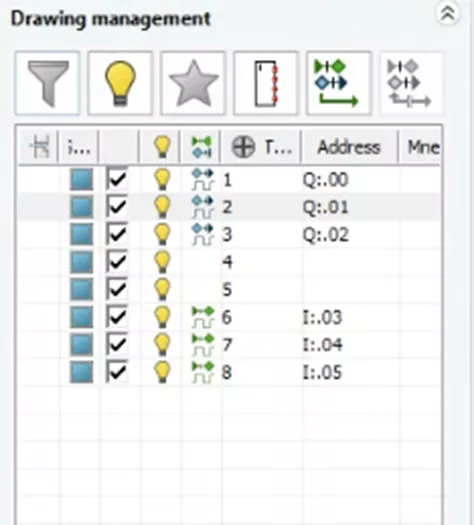
Directly beneath these tools is a list of your circuits and information about them. Choose which circuits to insert.
Once you are satisfied with your PLC settings, place the PLC into your drawing.
With that, you have completed your custom PLC and added it to your drawing. Get the most out of your SOLIDWORKS Electrical software by visiting the links listed below. Additionally, join the GoEngineer Community to create forum posts, enter design contests, and answer questions from other SOLIDWORKS users.
Editor's Note: This article was originally published in December 2017 and has been updated for accuracy and comprehensiveness.
Related Articles
SOLIDWORKS Electrical Save Manufacturer Part Info in a Symbol
How to Change SOLIDWORKS Electrical User Data
Reusing Wires in SOLIDWORKS Electrical Across Multiple Projects
Import Symbols into SOLIDWORKS Electrical from Other Systems
![]()
About Nathen Blas
Nathen Blas is a SOLIDWORKS Technical Support Engineer based out of our Headquarters in Salt Lake City, Utah. He earned his Bachelor’s degree in Mechanical Engineering at the University of Utah in 2018 and joined the GoEngineer family that same year.
Get our wide array of technical resources delivered right to your inbox.
Unsubscribe at any time.