SOLIDWORKS Flow Simulation: Solution Adaptive Mesh Refinement
SOLIDWORKS Flow Simulation can adapt the computational mesh to the solution during the calculation. The software splits the mesh cells into the high-gradient flow regions and merges the cells in the low-gradient flow regions. This ensures better accuracy during the calculation. The mesh starts from an initial state and is modified during the calculation based on user-defined settings.
Question: How do I enable the solution adaptive mesh refinement option?
Answer: This can be done in two different ways, during the initial setup of the Flow Simulation project and after the project has already been created.
Initial Project Setup
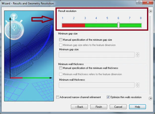
Setting the Result resolution slider bar to a level six or higher on the Results and Geometry Resolution screen of the Wizard automatically enables the solution adaptive mesh refinement option.
Post Project Setup
If the project was created without initially enabling the solution adaptive mesh refinement option in the wizard, it has to be turned on manually through the Calculation Control Options dialog window.
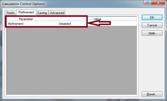
Calculation Control Options – Refinement tab
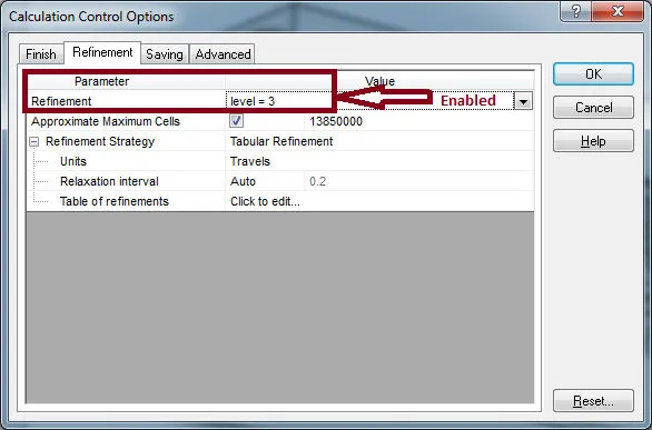
The Refinement level specifies how many times the initial mesh cells can be split to achieve the solution-adaptive refinement criteria. For example, if the refinement level is set to three, and there are two-level initial mesh cells, the solution adaptive refinement process can split these cells down to five-level cells.
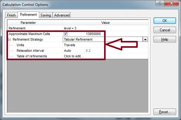
The Approximate Maximum Cells option allows for limiting the total number of cells created during the refinement process. This helps with making sure that the available amount of physical
RAM on the computer is not exceeded during the calculation.
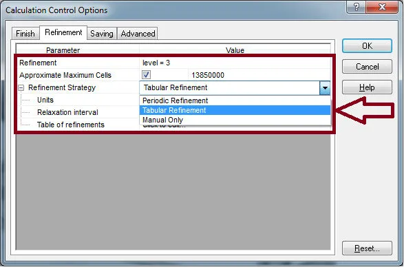
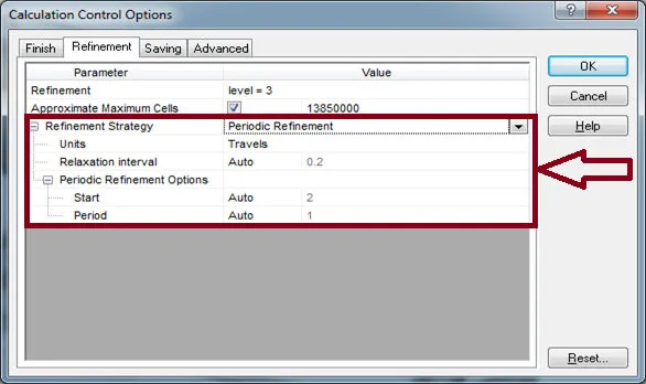
The Refinement Strategy option governs when the refinement takes place during the calculation. There are three options available, Periodic Refinement, Tabular Refinement, and Manual Only.
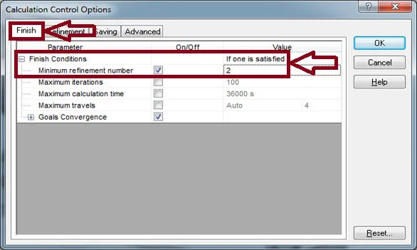
The periodic refinement settings allow for the specification of the start moment and the period over which the periodic refinements will be performed. Using the settings depicted below, the solution adaptive mesh refinement will begin at two travels. The calculations will progress for one travel at the current mesh and then perform another mesh refinement. The total number of mesh refinements is set on the Finish tab. This setting overrides the Finish Conditions value. If the value is set to “if one is satisfied”, the solution will still complete based on the refinement settings. The Relaxation interval specifies the additional length of calculation that is required after the last refinement occurs.
The table of refinements entity specifies the mesh refinement moments. The units for both automatic refinement strategies can be changed to iterations.
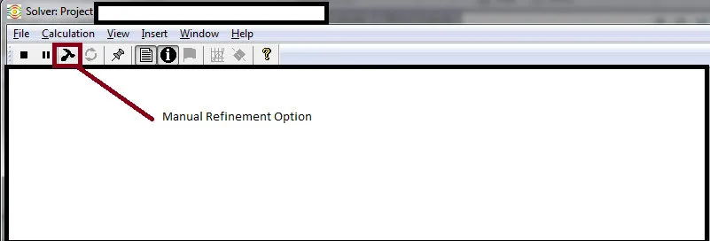
The manual only refinement option forces the user to manually specify when the refinement takes place by selecting the refinement button in the solver dialog window.
Using any of the processes listed in this document will allow a user to update the computational mesh to fit the solution during the calculation. This simplifies the tedious process of manually applying mesh controls to the model. Also, this ensures that areas of the model that need mesh refinement for better accuracy will receive them. For novice users, this simplifies the meshing process.
More SOLIDWORKS Flow Simulation Articles
Backspin is Important to Your Basketball Free Throw! A SOLIDWORKS Simulation Study
Cybertruck Simulation: Deal or Dud?
Tank Sloshing Using SOLIDWORKS Flow Simulation
SOLIDWORKS Flow Simulation Videos
![]() SOLIDWORKS Flow Simulation Tutorial - How to Isolate Parts in a Temperature Solid Plot
SOLIDWORKS Flow Simulation Tutorial - How to Isolate Parts in a Temperature Solid Plot
![]() SOLIDWORKS Flow Simulation Magnus Effect and Airfoils
SOLIDWORKS Flow Simulation Magnus Effect and Airfoils
![]() SOLIDWORKS Flow Simulation - Structural Analysis with CFD Results
SOLIDWORKS Flow Simulation - Structural Analysis with CFD Results
![]()
About GoEngineer
GoEngineer delivers software, technology, and expertise that enable companies to unlock design innovation and deliver better products faster. With more than 40 years of experience and tens of thousands of customers in high tech, medical, machine design, energy and other industries, GoEngineer provides best-in-class design solutions from SOLIDWORKS CAD, Stratasys 3D printing, Creaform & Artec 3D scanning, CAMWorks, PLM, and more
Get our wide array of technical resources delivered right to your inbox.
Unsubscribe at any time.