SOLIDWORKS Sensor Tool Explained
The SOLIDWORKS Sensor Tool allows a user to set parameters within a model or assembly that can then be monitored by SOLIDWORKS as your design is developed. If a design change you make results in a deviation outside the limits you specify, then the software will alert you, allowing for the appropriate action to be taken.
The sensors folder can normally be found in the feature manager tree.
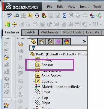
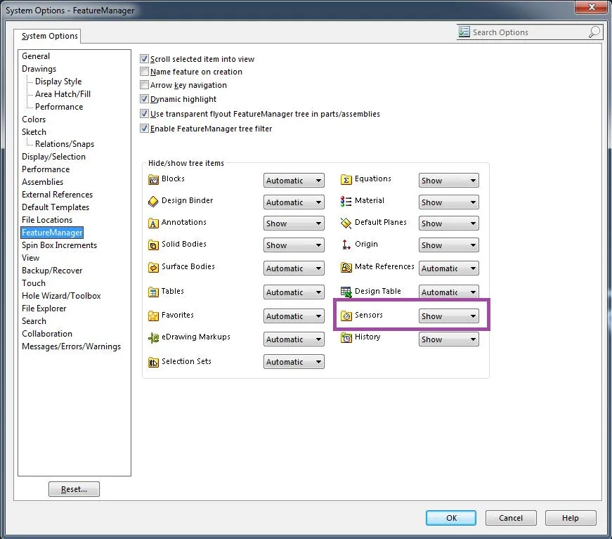
If you don’t have it, you can set it to show in your system options. (see below)
To demonstrate a sensor, we will take a look at a quick example model.
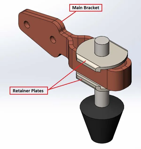
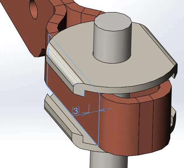
In this design, we want to monitor the clearance between the outer face of the Main Bracket and the inside face of the Retaining Plates to ensure that the product can always be easily assembled.
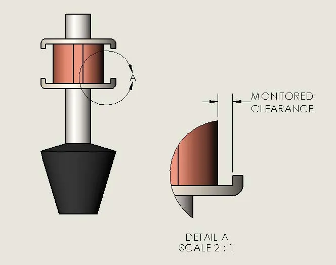
We will use a sensor to monitor the amount of clearance in this area. To do this we must first add a reference dimension. This dimension is what the sensor will reference.
To add a reference dimension, select the smart dimension tool from the sketch toolbar (you don’t need to be in a sketch).
Add the reference dimension between the outside face of the Main Bracket and the inside face of the Retaining Plate (the dimension should be shown in grey, denoting it as a reference).
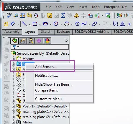
To add a new sensor, right-click on the sensor folder in the tree and select “Add Sensor” from the menu.
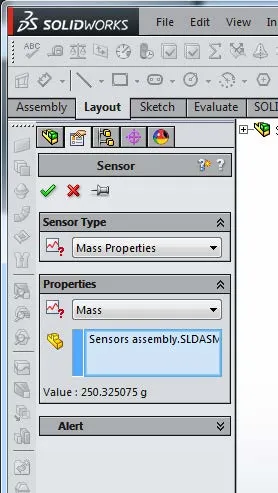
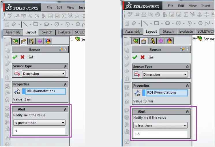
The sensor property manager will open (as shown below). We will now take a look at the parameters which can be set for Sensor Type, Properties, and Alert.
Sensor Type
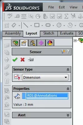
There are a number of sensor types to choose from including Simulation Data, Mass properties, Dimension, and Measurement. A description of each type of sensor is shown below. (Taken from SOLIDWORKS help) For this example, we are going to choose dimension from the list of sensor types.
Sensor types include:
Mass Properties - Monitors properties such as Mass, Volume, and Surface Area.
Dimension - Monitors dimensions you select.
Interference detection - (Available in assemblies only.) Monitors the assembly for interferences between components you select.
Proximity - (Available in assemblies only.) Monitors the assembly for interferences between a line you define and components you select. For example, use proximity sensors to model laser position detectors.
Simulation data - (Available in parts and assemblies, for use in SOLIDWORKS Simulation.) Monitors: Simulation data such as stresses, connector forces, and factors of safety on particular regions of the model Results from Simulation transient studies (non-linear, dynamic, and drop-test studies)
Properties
There are a wide variety of properties available for selection. Each sensor type has specific properties relating to it (there are numerous options, so take some time to see exactly what’s available). In our example, we will be using a dimension sensor. For the property, we simply need to select the reference dimension we added earlier. The value of the selected dimension is displayed.
Alert
If we wish for SOLIDWORKS to make us aware of any changes made to the dimension we are monitoring then we must select the alert check box. Here we can choose when we wish to be alerted of any changes. In this example, we want to be alerted if the value of our reference dimension falls below 1.5 mm or larger than 3.0 mm (see settings in the image below).
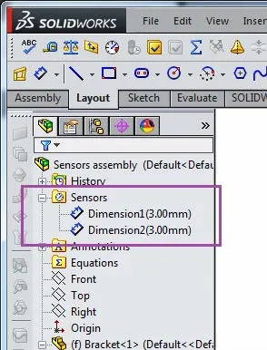
With all the settings made, close the sensor property manager using the green check and continue with the design. Notice that the sensor folder in the feature tree contains the dimension sensors we just configured.
I open up the Retaining Plate part and modify the recess from 26mm to 22.5mm; exit the sketch and update the model.
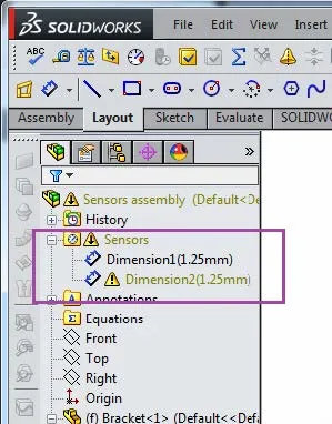
Returning to the assembly, I can see the effects of the modification to the Retaining Plate. You will notice that there is now an error in the feature tree.
The sensor has been triggered due to the design change made to the Retaining Plate, resulting in a warning in the feature tree that I can now react to. Relevant changes can then be made to ensure the design is in keeping with the sensor values.
As you can see with this process, the use of Sensors can help with design criteria being directly incorporated into the design of parts and assemblies and gives you the ability to be notified when constraints are out of the requested tolerances specified.
I hope these tips and tricks help you with using the SOLIDWORKS Sensor tool in your design.
More SOLIDWORKS tips and tricks
SOLIDWORKS Combine Feature Tutorial
Working with Exploded Views in SOLIDWORKS
Inserting Model Dimensions into a SOLIDWORKS Drawing
Scaling a Part in SOLIDWORKS 2 Different Ways
![]()
About GoEngineer
GoEngineer delivers software, technology, and expertise that enable companies to unlock design innovation and deliver better products faster. With more than 40 years of experience and tens of thousands of customers in high tech, medical, machine design, energy and other industries, GoEngineer provides best-in-class design solutions from SOLIDWORKS CAD, Stratasys 3D printing, Creaform & Artec 3D scanning, CAMWorks, PLM, and more
Get our wide array of technical resources delivered right to your inbox.
Unsubscribe at any time.