SOLIDWORKS Simulation Mesh Convergence in Frequency Analysis
A Frequency Analysis in SOLIDWORKS Simulation gives two outputs:
- The natural frequencies of whatever design you are analyzing.
- The shape that each natural frequency creates in the structure. These shapes are called mode shapes.
In this article, we explore how changing the solid mesh density of the analysis could change the program’s ability to accurately calculate the design’s natural frequencies and mode shapes.
Is Meshing Important in a SOLIDWORKS Simulation Frequency Analysis?
Many people don't realize how much the mesh can affect the accuracy of frequency analysis results. In some cases, where the objects under analysis are bulky, changing the mesh density does not affect the results; however, in objects with thin-walled structures, changing the mesh density can have a significant impact. Even mode shapes can be affected since a mesh that is too coarse may not allow a structure to bend or deform naturally.
Meshing a Bracket for Frequency Analysis
Let’s take a simple bracket and run it through an example frequency analysis.
In the image below, we see the different levels of mesh used in this simple bracket.
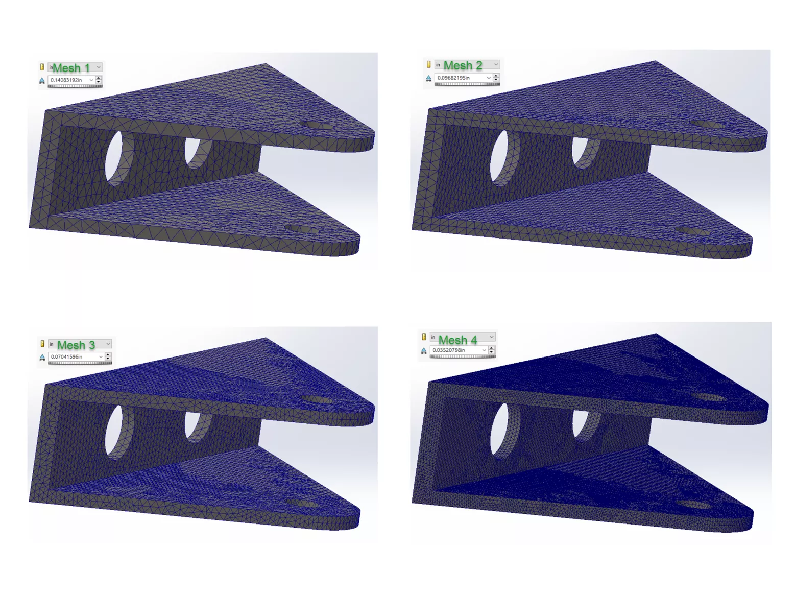
Figure 1: Different mesh densities in four simulation studies
Figure 2 shows the same simulation studies in the same order as the meshes shown in Figure 1. As you can see, five natural frequencies are shown for each study. As the mesh density increases, the natural frequency tends to decrease. This is because many elements are needed to capture the natural bending and twisting that occurs in real structures. If there are too few, these elements restrict the deformations, resulting in an artificially stiff model. As the mesh density increases, the mesh can properly capture the actual stiffness and natural frequencies of the structure.
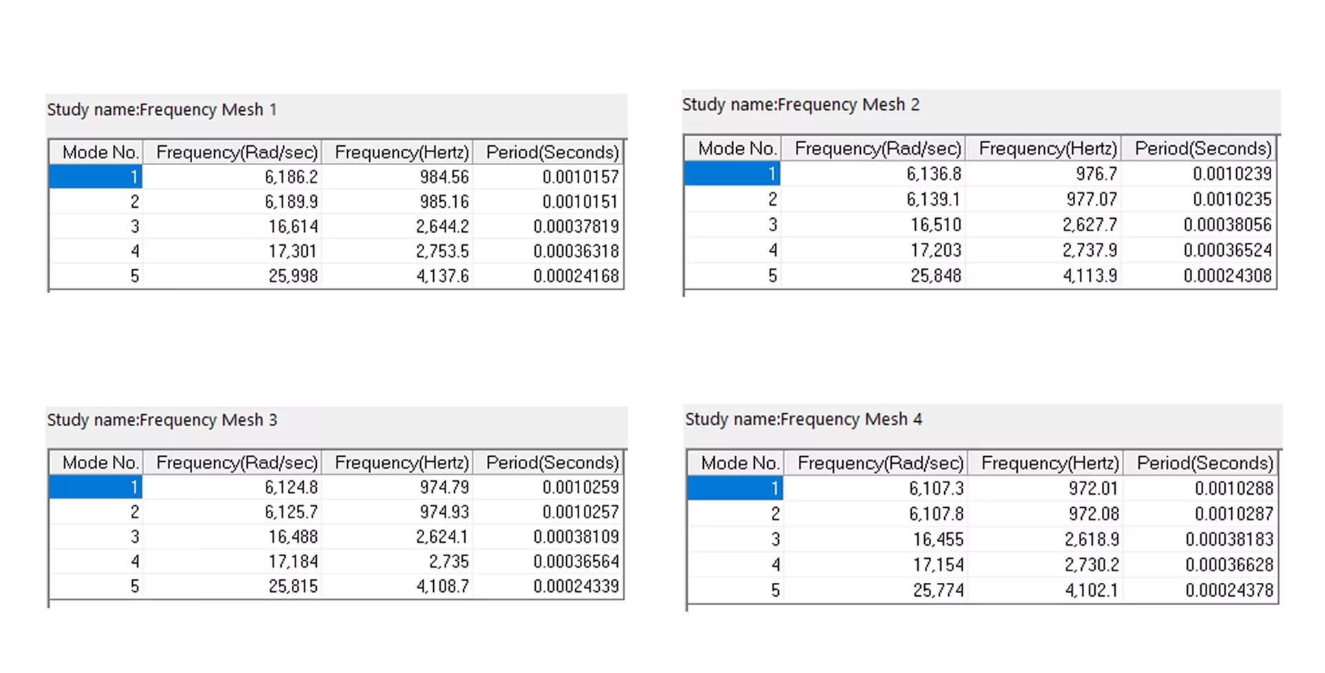
Figure 2: First five natural frequencies for the four mesh simulation studies analyzed
The figure below shows only the first natural frequency and its mode shape for the four different mesh density studies. As you can see, the mode shape of this first natural frequency remains the same. This indicates that it's not always the case that the mode shape order changes, but if you are solving for more than the first five modes, you may see some shuffling of the mode shape order.
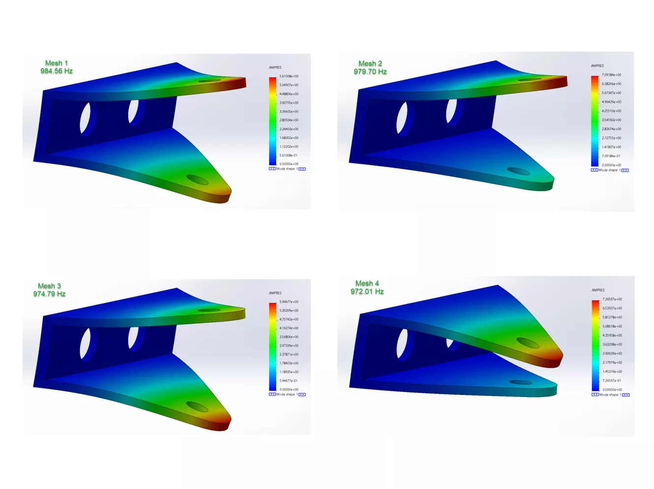
Figure 3: Mode shape for the first natural frequency of the four different mesh density studies
Note: Draft Quality mesh should typically be avoided in Frequency Analyses.
In Figure 4, we have the results of a Draft Quality mesh (same mesh density as the Mesh 4 study above). As you can see, the results show a higher frequency than any of the Mesh 1-4 studies. Draft Quality meshes tend to require substantially more refinement and, therefore, more overall solve time to obtain accurate results.
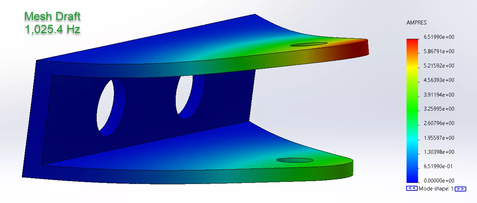
Figure 4: Results of a mesh 4 level density with Draft Quality mesh
In our next SOLIDWORKS Simulation frequency analysis article, we'll discuss how using shell elements in a frequency analysis differs from using solid elements, and if shell elements are beneficial or not. Stay tuned!
SOLIDWORKS Simulation Training
Sharpen your Simulation skills by enrolling in the official SOLIDWORKS Simulation Advanced Trainig Course from GoEngineer. In this course, you'll learn even more about Frequency analyses plus additional topics including topology, buckling, fatigue, and drop test analyses.
More SOLIDWORKS Simulation Tutorials
SOLIDWORKS Simulation Frequency Analysis Comparison Between FEA and Real Life
SOLIDWORKS Simulation Nonlinear Material Model Type Setup
SOLIDWORKS Simulation Natural Frequencies, Mode Shapes, and Vibration Explained
What is Topology Optimization - SOLIDWORKS Simulation
Solving Mesh Failures in SOLIDWORKS Simulation with Mesh Controls

About Taran Packer
Taran is a SOLIDWORKS Simulation Technical Support Specialist at GoEngineer. He has a Bachelor’s degree in Biomedical Engineering from the University of Utah. Taran enjoys learning about different tools in SOLIDWORKS Simulation, Flow Simulation, and Plastics.
Get our wide array of technical resources delivered right to your inbox.
Unsubscribe at any time.