SOLIDWORKS Simulation Natural Frequencies, Mode Shapes, and Vibration Explained
One important consideration when studying a design is how natural frequencies can cause structures to undergo resonance. This effect became famous back in 1940 when the cause of the Tacoma Narrows bridge collapse is still studied by many engineering schools today. Fast forward to the present, SOLIDWORKS Simulation Natural Frequency Analysis is included as part of the Simulation Professional package. Not only will this allow designers to analyze this behavior, but the results are relatively easy to obtain.
Observing the Natural Frequencies
Before we begin, the main factors considered in a frequency study are as follows:
- Geometry
- Fixtures/Support
- Loads vs. no loads
- Material (density)
Related Article >> SOLIDWORKS Simulation Frequency Analysis Comparison Between FEA and Real Life
Frequency Values with Rigid Support (Plastic)
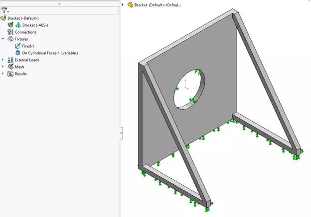
To demonstrate, below is a simple motor mount with supports. The geometry consists of a thin leg structure made with strong plastic material. The bottom will remain stationary with no loads applied.
The first mode shape demonstrates the fundamental frequency (the lowest frequency) where the object first exhibits this effect. In SOLIDWORKS, we can animate this to get a better picture of how the frequency causes the object to oscillate. We can use the results obtained by SOLIDWORKS Simulation to design around the dynamic effects of the motor where it would resonant a frequency in the same area.
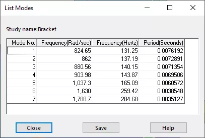
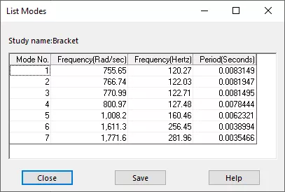
The other modes can generally be described as the higher natural frequencies to which the same phenomenon will occur at their specific values. With SOLIDWORKS Simulation, the values are all listed in a simplified table making it easy for anyone to interpret.
Mode Shape 1
Mode Shape 2
The mode shapes will vary in animation based on the next frequency value obtained. This information can be useful to indicate which areas of the structure may oscillate.
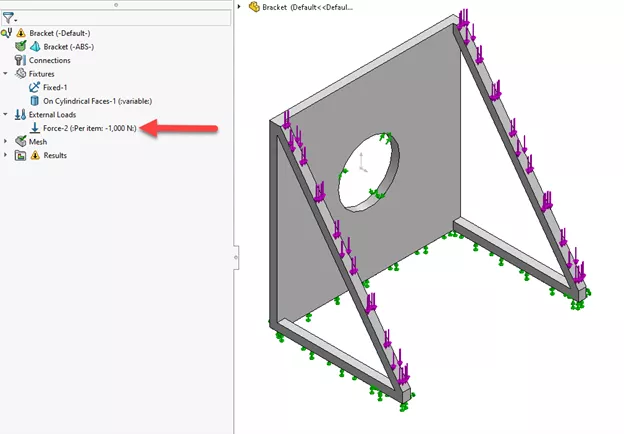
Frequency Values with Supports & Load
Another consideration is that by adding a load, the model can also undergo changes in stiffness which can alter the natural frequency values. Applying this to the legs of the bracket has caused the structure to lose some stiffness, and the fundamental frequency (mode no. 1) drops from 131 to 120 hertz.
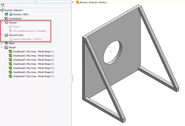
Frequency Values with No Loads & No Supports
A similar situation can occur when the study contains no loads or fixtures in the setup.
The first six mode shapes will have zero frequency corresponding to the free rotations and translations along XYZ. Any mode shapes after the seventh are considered as the elastic modes.
In SOLIDWORKS Simulation, these mode shapes are compiled based on the previous rigid mode shapes calculated.
Mode Shape 7
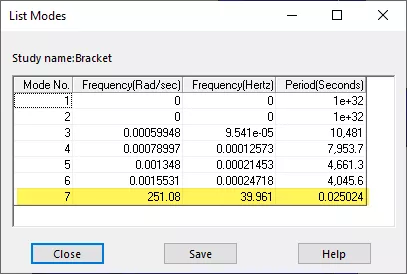
Without any rigid support, the fundamental frequency of this model has decreased considerably and may undergo oscillations sooner.
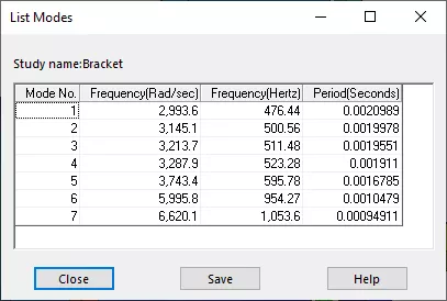
Frequency Values different Material (Steel)
We can change the material from plastic to steel to see how the mass density affects the frequency values. As shown, the new range of values will differ and may have a broad range.
Vibration Analysis
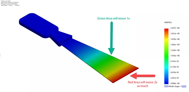
Another feature of SOLIDWORKS Simulation is to study the vibration effects of a model. In a real-world example, this scraper will be supported on one end and a blunt force (dynamic loading) applied on the other. The mode shape implies that without proper damping, the blunt force would cause this to undergo infinite oscillating cycles.
When setting this up in a frequency study, no loads are applied, making the object free to vibrate.
By studying the amplitudes on the plot, the area in red would displace approximately twice the amount as the green area.
Related Article >> Frequency Study Plot with SOLIDWORKS Simulation
This free vibration demonstrates the effect to where the displacement will be relative to the dynamic loading (actual force) applied and the mode shape generated by the impact. Given this, dynamic loading can then be set up which is available in the SOLIDWORKS Simulation Premium package to get the true displacement values.
To watch a demonstration of these tools, check out the video below.
More SOLIDWORKS Simulation Tutorials
How to Set Up a Thermal Study in SOLIDWORKS Simulation Professional
SOLIDWORKS Simulation Drop Test Tutorial
Free SOLIDWORKS Simulation Tutorials
What's New SOLIDWORKS 2022: Simulation, Flow, & Plastics

About Jackie Yip
Jackie Yip is a Technical Support Engineer at GoEngineer. When Jackie isn’t assisting customers or teaching a SOLIDWORKS Essentials class, he enjoys road biking and keeping up on the latest tech trends.
Get our wide array of technical resources delivered right to your inbox.
Unsubscribe at any time.