SOLIDWORKS Simulation Stabilized 3-Point Bending Test Setup
This example of a 3-point bending test serves to show how SOLIDWORKS Simulation requires considerations to provide model stability and methods to provide that stability.
General Setup
In this setup, two rectangular bodies are created as supports with fixtures applied to their bottom faces and a single point load applied in the center of the top of the bar as shown in Figure 1.
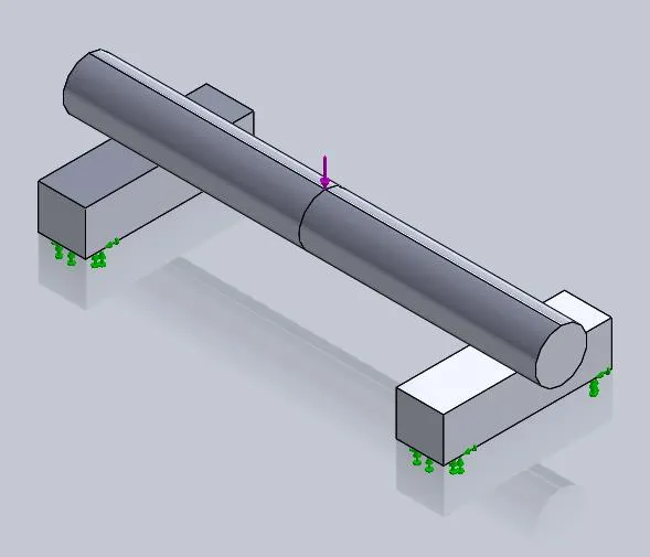
Figure 1: 3-point bending test on a symmetric model
A 'No Penetration' contact is applied between the bar and the two supports such that the force pushes the bar into the supports and is bent. The result is known to be symmetric but the results from this initial setup show that the bar deflects oddly as though it were rotating in addition to bending (shown in Figure 2).
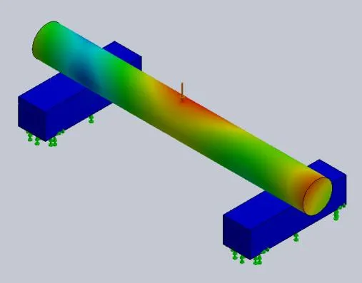
Figure 2: Resultant displacement plot from whole, unstabilized model
Related >> No Penetration Contact Set Setup
It is for this reason that this model should be forcibly stabilized to produce a symmetric result. In doing so, considerations have to be taken to make sure adjustments to the model do not lead to the program giving invalid results.
Option 1: Utilize Symmetry to Stabilize Model
In situations where the model itself and the loading are symmetric, then symmetry should be used within the simulation. Symmetry fixtures in SOLIDWORKS Simulation are relatively non-evasive restraints that prevent stress singularities from generating while also stabilizing 1 translational and 2 rotational degrees of freedom in the model.
Figure 3 shows the model bisected along the long plane of symmetry. The planar faces produced from cutting the model in half then have a “Symmetry” type fixture applied to them (found under ‘Advanced Fixtures’).
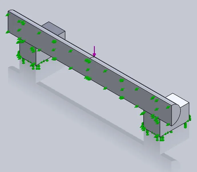
Figure 3: Half model setup using symmetry restraint on cut faces
The program will interpret the behavior of this analysis setup as a whole piece but the results will reveal that the displacement is now symmetric as expected in Figure 4.
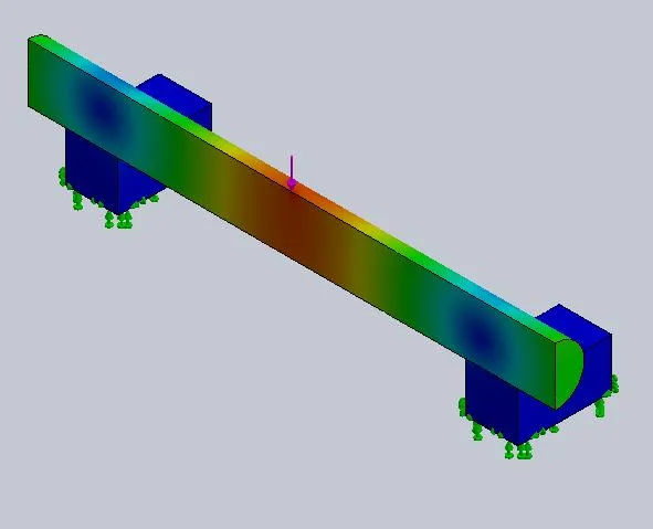
Figure 4: Resultant displacement plot from half model stabilized by symmetry fixture
Given that this is a half model, the forces applied to the model will need to be set to half their value to be analogous to the full model. This does not need to be considered for pressure loads though.
This symmetry setup can be taken a step further by utilizing a quarter symmetry model as well as shown in Figure 5.
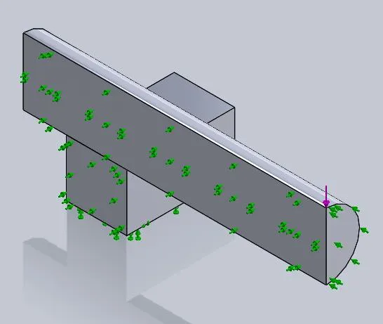
Figure 5: Quarter model setup using symmetry restraint on cut faces
The quarter model produces the same results as the half model with the benefit of either using fewer mesh elements and having a faster solve time or having a denser mesh producing, generally, better results.
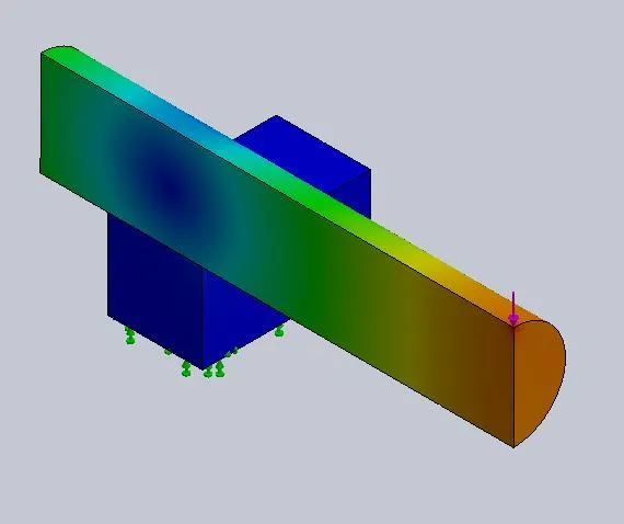
Figure 6: Resultant displacement plot from quarter model stabilized by symmetry fixture.
Option 2: Stabilize the Full Model
In many cases, the use of symmetry is not possible due to the model being asymmetric. Because of this, other fixture techniques need to be utilized to stabilize the full model and produce valid results.
In this next example, the item being bent is not a uniform bar but a bar that has an asymmetric bulb placed on one side as seen in Figure 7.
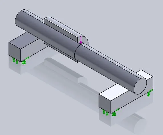
Figure 7: 3-point bending test on an asymmetric model
This full model, likewise, suffers from rotation when not stabilized as shown in Figure 8.
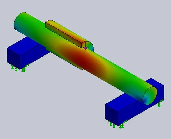
Figure 8: Resultant displacement plot from whole, un-stabilized asymmetric model
The remedy is to create fixtures on the model at locations that would have a minimal impact on the results. This leads to the fixtures being placed on the likely locations of pseudo-symmetry (positions which theoretically should displace the least in a given direction on the model).
For this model, a split line curve is placed on the model to produce vertices at these locations for use with custom 'Use Reference Geometry' fixtures. These fixtures are defined to prevent movement on the pseudo-symmetry vertices to prevent the model from sliding/rolling on the support blocks as shown in Figure 9.
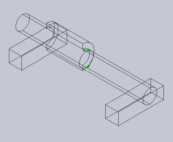
Figure 9: Locations defining the placement of the stabilizing fixture at points of pseudo-symmetry
The effect of these stabilizing fixtures shows in the displacement plot where the model once again shows a normal bending pattern (as seen in Figure 10).
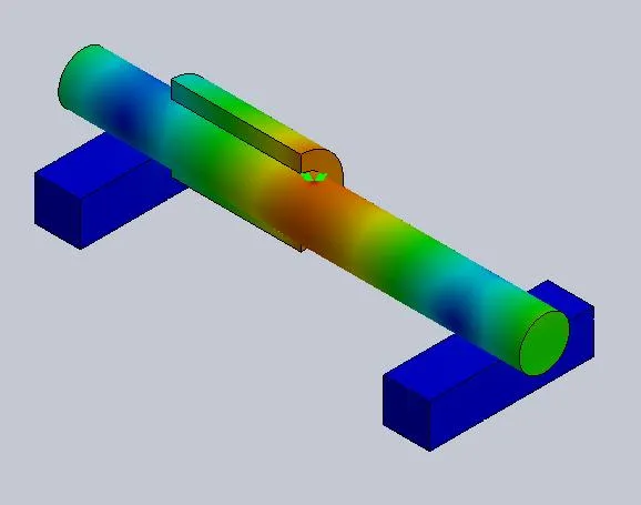
Figure 10: Displacement plot from stabilized asymmetric model
Conclusion
The impact of stabilizing models using either symmetry models/fixtures or stabilizing vertex fixtures can lead to more reliable results from SOLIDWORKS Simulation.
I hope you found this example of a 3-point bending test in SOLIDWORKS Simulation helpful. Check out the related articles below to learn more about this tool.
More SOLIDWORKS Simulation Tutorials
SOLIDWORKS Simulation Gauss Points, Nodal, and Element Stress
Troubleshooting SOLIDWORK Simulation No Penetration Contact Sets Recommendations

About Ryan Dark
Ryan has been in the GoEngineer technical support team since February 2008 where he most notably provides support for all FEA and CFD software offered by SolidWorks. His most recent accolade is the title of Elite Application Engineer awarded by SolidWorks Corp.
Get our wide array of technical resources delivered right to your inbox.
Unsubscribe at any time.