SOLIDWORKS Simulation: Troubleshooting Why a Single Part Will Not Mesh
What to do if your mesh fails on a single part in SOLIDWORKS Simulation?
I should note that this method only works in part files. It will not work in an assembly file. If your assembly file is not meshing correctly then please view this video on Mesh Controls. If you can narrow down your search to a single part that is not meshing correctly, then this document will help you find what in that specific part is keeping SOLIDWORKS Simulation from meshing the part. If a single part will not mesh, there are several techniques that you can utilize to figure out why it will not mesh:
- Try using the other mesh parameter in the “Create Mesh” command manager such as “Curvature based mesh”. Sometimes when one mesh parameter fails the other will work.
- Try meshing with coarse versus a fine mesh and vice versa
- Lastly, if you know where the problem area or areas are, you can apply mesh control to these areas, or model these areas differently so that they mesh correctly.
If the above methods fail, and you do not know where the problem areas are, then you could also try the Spit Command to narrow down your search for the problem areas.
How to narrow your search for geometric problem areas using the Split Command
First, go back into your model tab and create a new sketch on a plane of your choice. Make a linear pattern of vertical lines that cover the entire model. The point of this is to split the model into sections. Once you have made the sketch with lines splitting your part, activate the “Split” Command by clicking on Insert > Mold > Split.
Once in the “Split” Command Manager, make sure that the sketch you just made with multiple lines going through your part file is selected in the “Trim Tools” box.
Then click on the “Cut Part” button. All of the different sections that can be made using your sketch will show up under the “Resulting Bodies” selection field. Check all of the boxes in the list and press the green checkmark as shown in Figure 1 below.
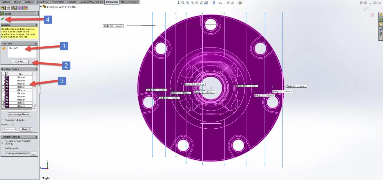
Figure 1: Split Command
Now that your part has been split into sections, go back to your Simulation tab and re-mesh the model. Your mesh will fail like the first time, except this time you can right-click “Mesh” and click “Show Mesh” Now all of the slices that meshed properly, will show up leaving the slices that did not mesh out, as seen below in Figure 2.
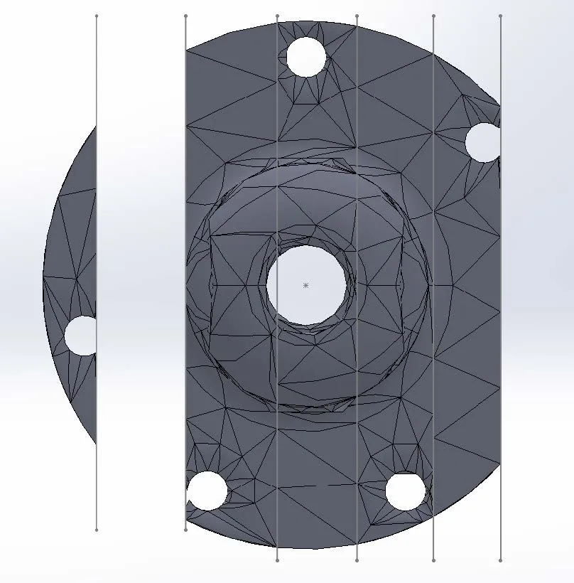
Figure 2: Split Part with Mesh
Now that you now know the sections that are not meshing properly, you can go back to your model and put more lines in the sketch that you are using to split up your part into multiple bodies. Only focus on the parts of the model that are not meshing, as shown in Figure 3.
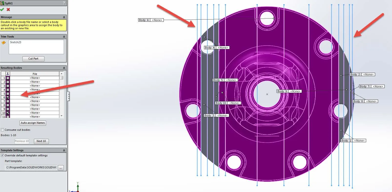
Figure 3: Non Meshing Sections
The new lines are automatically included in the “Resulting Bodies” list of your previously created “Split” Command, but they need to be checked to become separate bodies.
Mesh the model again in the Simulation tab. Repeat the above process until you have a small enough piece or pieces of the model that will not show up using the “Show Mesh” command. These small areas represent the small area or areas that are causing the mesh to fail.
At this point, you either need to apply mesh control to these problem areas or you need to fix the faulty geometry that will not allow the part to mesh. Different types of faulty geometric areas that can be found in part models are knife edges or invalid faces.
After you have applied mesh control or fixed the faulty geometry in the models, problem areas of your split sections will mesh. As you can see below in Figure 4, I was able to get my whole model to mesh by applying mesh controls for a denser mesh to the fillets around the perimeter holes.
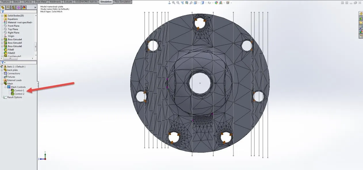
Figure 4: Specified Mesh Control and Faulty Geometry Cleanup
You may now go back into your model tab and suppress the “Split” command in your feature design tree. Now mesh the model as a whole body. Once this part meshes as a whole, you can be certain your problem has been fixed. This part will now mesh either on its own or in an assembly when you apply the same mesh controls in the assembly model to this part. The same principle applies if you rebuild the part in the assembly after making changes to its geometry.
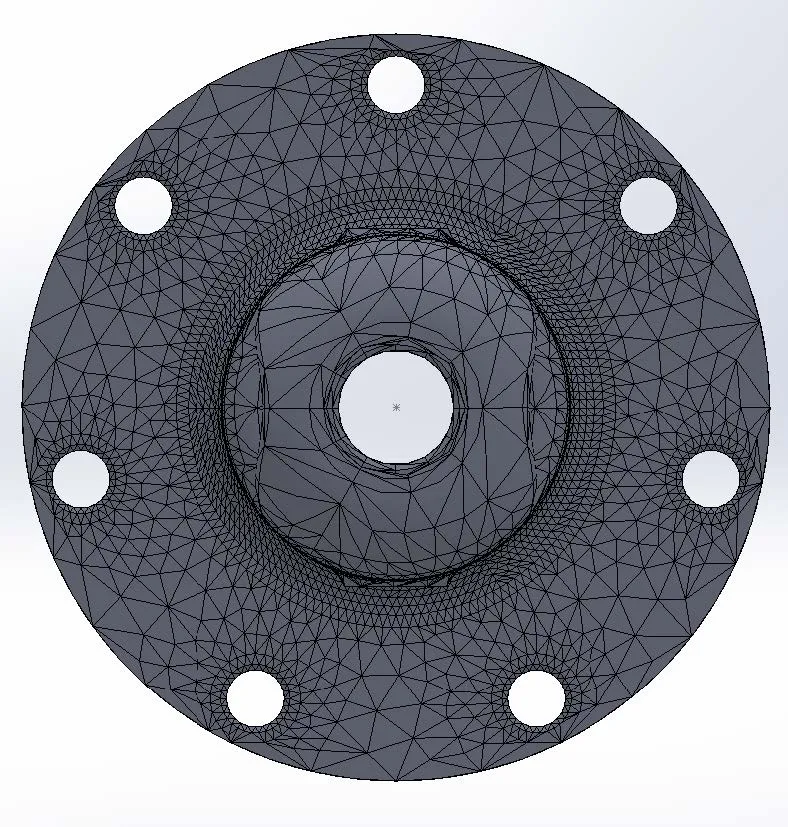
Figure 5: Meshed Part
Expand Your SOLIDWORKS Simulation Skillset
Draft Quality & High-Quality Mesh SOLIDWORKS 2020 - New!
Troubleshooting SOLIDWORKS Simulation No Penetration Contact Sets Recommendations
Piecewise Nonuniform Pressure in SOLIDWORKS Simulation
Changing Units and Number Formats in SOLIDWORKS Simulation
A Guide for Using Bearing Connectors in SOLIDWORKS Simulation

About Taran Packer
Taran is a SOLIDWORKS Simulation Technical Support Specialist at GoEngineer. He has a Bachelor’s degree in Biomedical Engineering from the University of Utah. Taran enjoys learning about different tools in SOLIDWORKS Simulation, Flow Simulation, and Plastics.
Get our wide array of technical resources delivered right to your inbox.
Unsubscribe at any time.