SOLIDWORKS Visualize: Applying Textures & Texture Mapping
Textures add depth and interest to everything from food to art, and the same is true for Visualize Appearances. Without textures, surfaces in Visualize can look flat or unrealistic, so let’s look at ways we can add and manipulate textures in SOLIDWORKS Visualize.
Texture Channels
SOLIDWORKS Visualize has four channels in which you can apply textures to an appearance: Color, Specular, Alpha, and Bump.
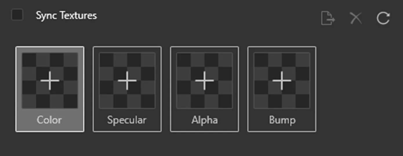
These channels use images (typically grayscale) to determine a specific property of the appearance (e.g., reflectivity or transparency).
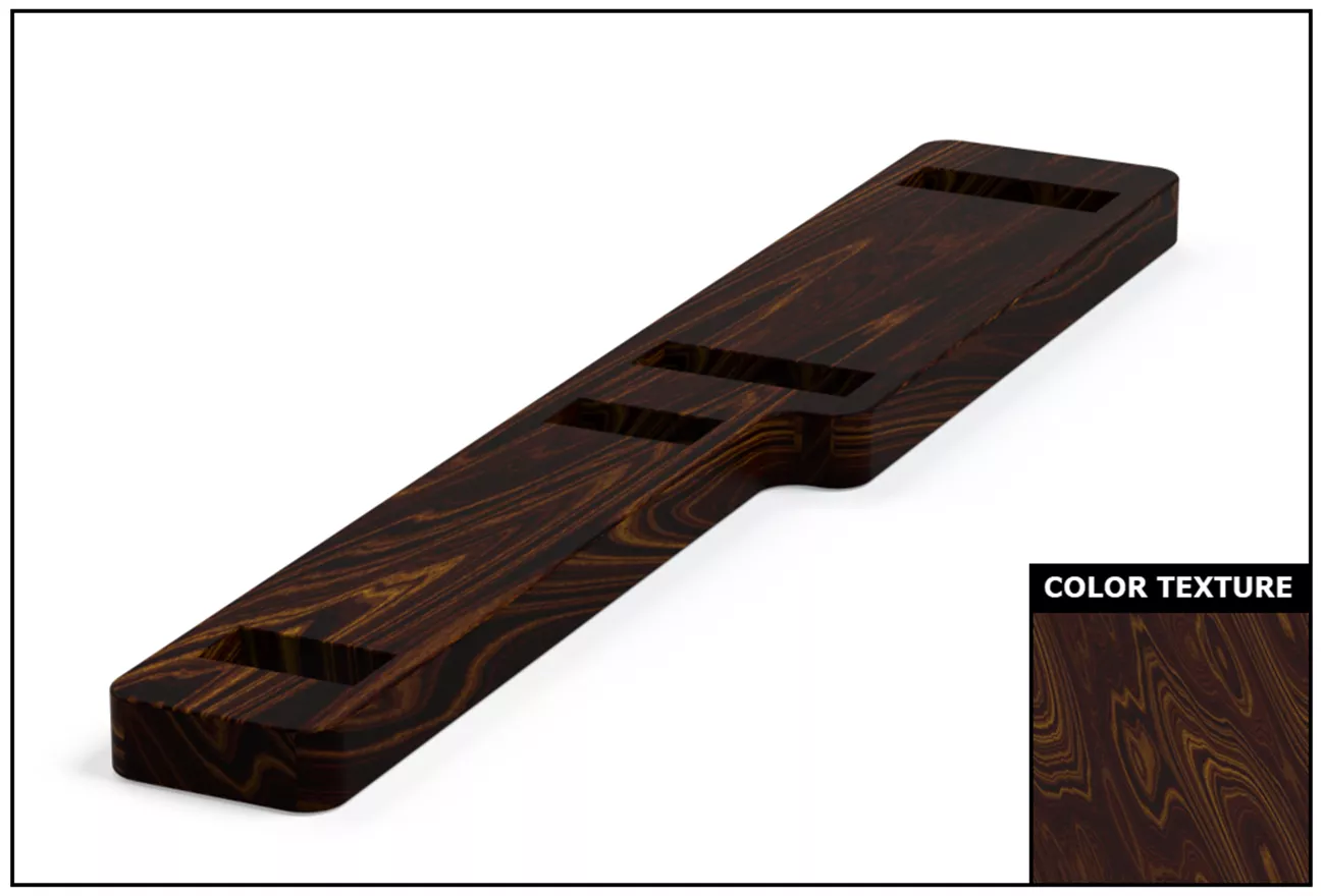
Color
The Color channel is not limited to grayscale and can work in combination with the appearance color. Using the Color texture channel can add a range of colors to a single body or gradients and patterns. A great example of using the Color channel is adding a wood texture.
Specular
The Specular channel is for controlling which areas are reflective and which are not. The darker areas of a texture will be duller and less reflective, while the lighter areas will have higher reflectivity. This effect can sometimes appear subtle or only noticeable under certain lighting conditions. The Specular channel will help prevent a part from looking too glossy or matte when reflecting light.
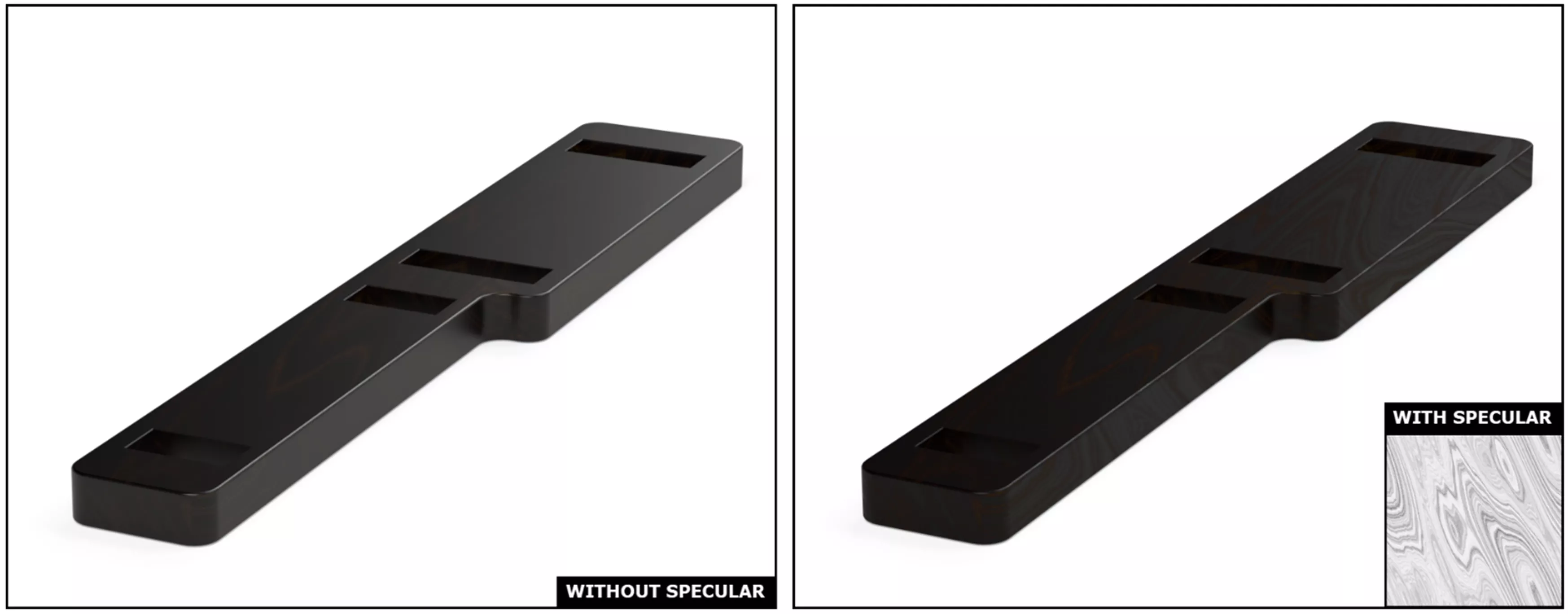
The Specular channel is also great for adding imperfections such as scratches or smudges that would be less reflective on a smooth surface.
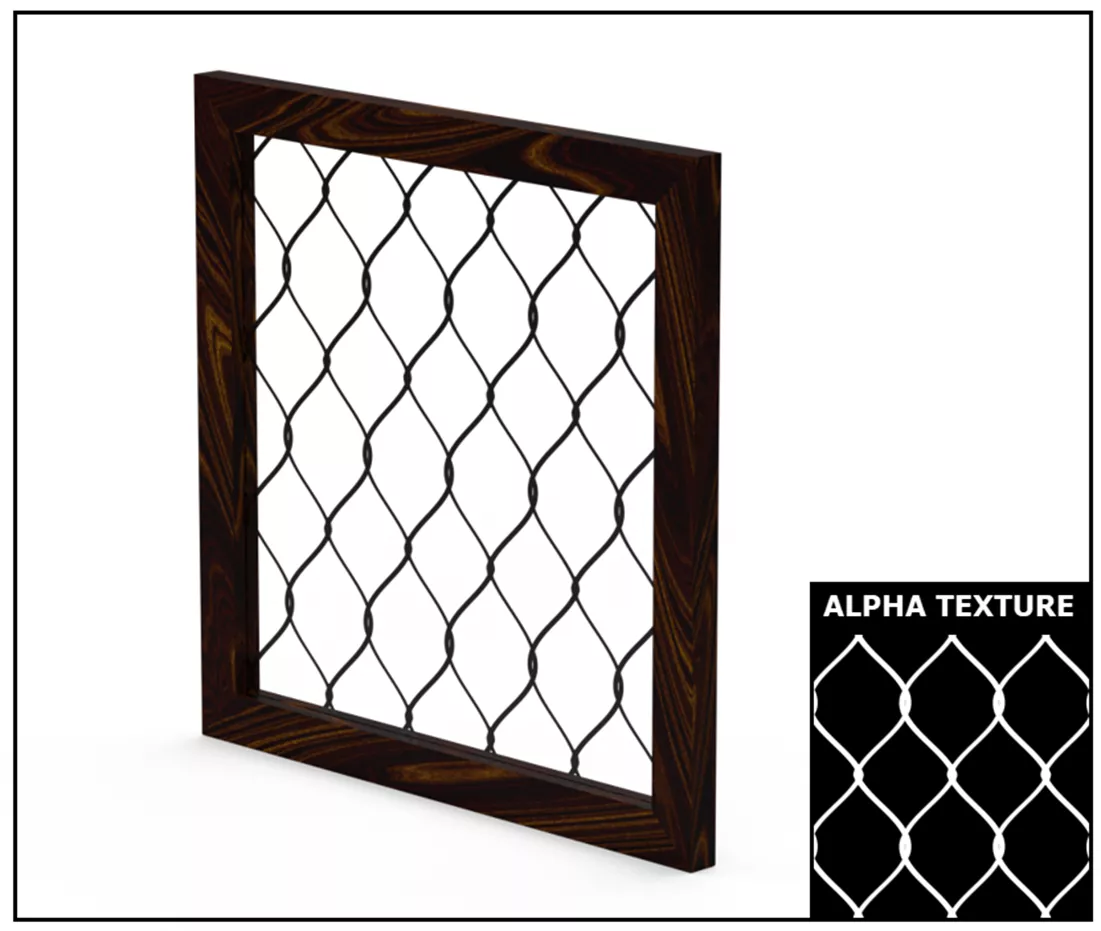
Alpha
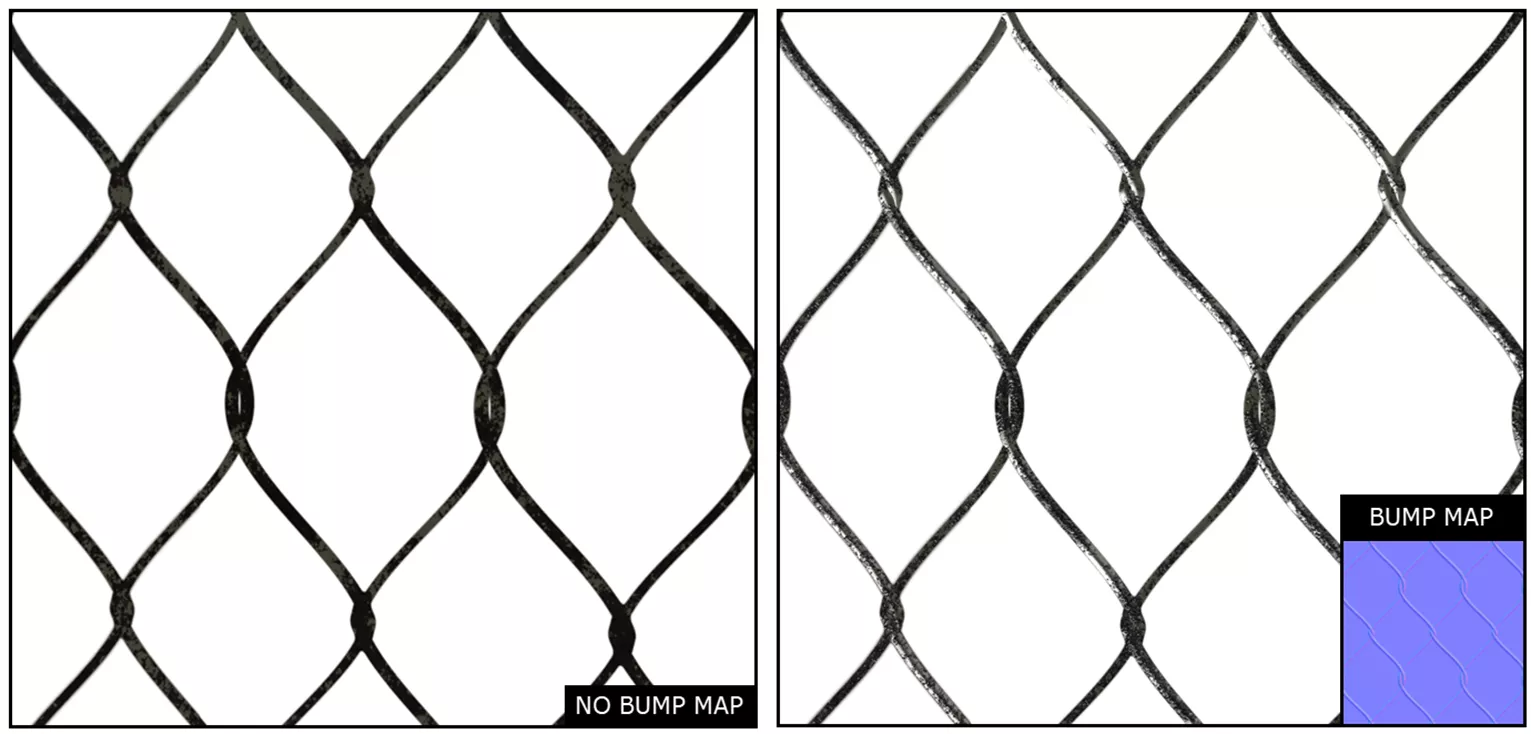
The Alpha channel is used to determine transparency. The white areas of the texture are fully transparent, and the black areas are fully opaque. This can be useful for creating patterned elements without having to model them (e.g., chain link fencing).
Bump
A Bump map is a way to add depth to an appearance even if the geometry itself is flat.
Within Bump, there are three subtypes: Bump, Normal, and Displacement. Each with its advantages and disadvantages.
For instance, Bump maps are grayscale and, while easier to create, the illusion of depth they create can be dependent on certain camera angles. For Bump maps, darker spots are the low points on the surface and lighter spots are the high points on the surface.
Normal maps are a more advanced version of Bump maps and the depth they create is better maintained through different camera angles. The downside of Normal maps is that the texture files are harder to obtain, usually requiring other programs to bake a Normal map from more complex geometry. The image below shows what a Normal map would look like, typically having a rainbow colored appearance.
Lastly, Displacement maps function similarly to Bump maps (dark spots are low points, and light spots are high points). The main difference is that where a Bump map simulates geometry, Displacement maps physically affect the geometry. These can be trickier to use and work best with higher-resolution textures.
What is Texture Mapping?
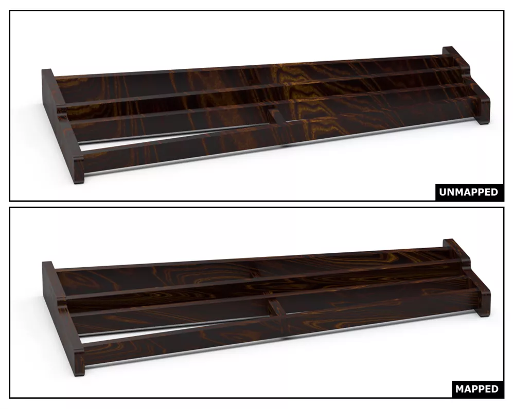
After textures have been applied to the appropriate channels to get the desired appearance, the next step is mapping those textures to the geometry itself. Texture Mapping is how the 2D texture image is placed/oriented onto the model geometry.
For example, this is essential to anything made of wood since wood grain direction is important.
Below are two images where one is the default orientation of the wood texture and is unmapped, and the other has been mapped for each body to create variation. Since no two pieces of wood are going to look identical, it is important to create this variation by scaling and moving the texture map.
How to Use Texture Mapping
When mapping a texture, there are a few options for the base shape called a Mode. Some examples are Box, Planar, Spherical, and Cylindrical.
Keep in mind that most texture images come as a square or rectangle, so when using more complex curved mapping types, like Spherical, there may be some minor stretching that occurs.
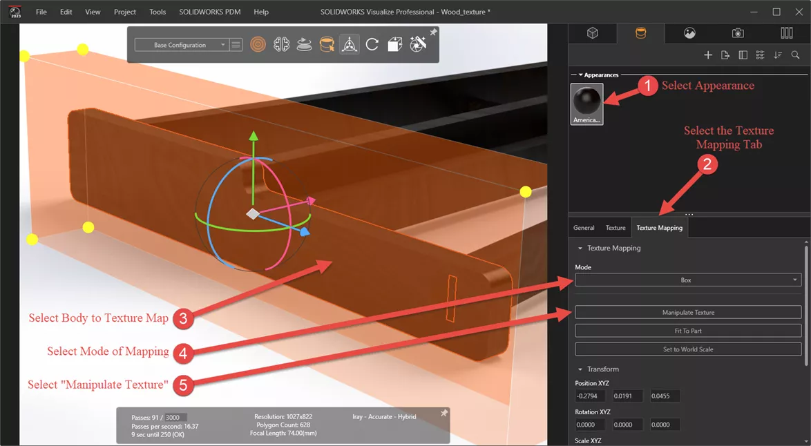
When mapping a texture, it is applied to the specific body that is selected during the process. Multiple bodies can have different mapping applied, even though they share the same appearance. The steps for mapping textures on a body are as follows:
- Select the Appearance that contains the textures you want to map.
- Select the Texture Mapping tab below your appearances.
- Select the body you wish to adjust the Texture Mapping for.
- Select which Mode you want the mapping to use (e.g., Box or Planar).
- If you do not see a preview for the mapping in your graphics area, click Manipulate Texture to toggle on the Manipulate tool.
After completing the above steps, click on the various handles to move, rotate, and scale the texture mapping shape.
Where to Get Textures
Stock textures included with SOLIDWORKS Visualize and in the following location:
%userprofile%\Documents\SOLIDWORKS Visualize Content\Textures
This selection is a bit limited but is a good place to start experimenting. For a wider selection, there are many websites to choose from.
The wire fence texture used to display the functionality of Alpha and Bump maps was obtained from Share Textures. Some other popular choices are Poly Haven and Poliigon, though some sites may require a membership or sign-in.
Now that you know what texture types there are, how to use them, and where to get them, it is time to make some renders! I hope you found this article explaining applying textures and texture mapping in SOLIDWORKS Visualize helpful. Check out more tips and tricks listed below. Additionally, join the GoEngineer Community to participate in the conversation, create forum posts, and answer questions from other SOLIDWORKS users.
Visualize Training
Want to take your SOLIDWORKS Visualize skills to the next level? Our SOLIDWORKS Visualize training course covers how to leverage 3D CAD data to create photo-quality content in the fastest and easiest way possible, from images to animations, interactive web content, and immersive virtual reality.
Learn More About SOLIDWORKS Visualize
The Perfect 3D Printed Desk Organizer: From Render to Reality
How the SOLIDWORKS Visualize Denoiser Tool Works
How to Fade Geometry in SOLIDWORKS Visualize Professional
![]()
About Braden Leasure
Braden Leasure is a Sr. SOLIDWORKS Technical Support Engineer at GoEngineer.
Get our wide array of technical resources delivered right to your inbox.
Unsubscribe at any time.