Understanding Thermal Expansion with SOLIDWORKS Simulation
I recently talked to a customer with validation concerns about an analysis - were the results and setup correct? With SOLIDWORKS Simulation and Simulation Professional, it is possible to verify the phenomenon of Thermal Expansion using Static Analysis tools. In this article, I'll compile the methods I used to diagnose and assist this customer's concern.
- Suggested Article >> Introduction to Validation Equations in SOLIDWORKS Simulation
First, we will go over some theory and hand calculations, then, we will see how to properly set up our simulation and review the results.

Theory and Hand Calculation
Let’s review the basic thermal expansion equation. If you recall, materials expand when introduced to thermal energy, causing the molecules to get excited and increase their total displacement within a lattice structure.
For linear expansion, we can illustrate thermal expansion as the fraction of change in length of a part being equal to the coefficient of expansion for that part’s material multiplied by the change in temperature of that part. Simply put, we illustrate this as:
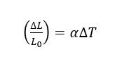
(Figure 1.1)
For this example, we will introduce our part that is made of AISI 304 to thermal energy, raising its temerature to 100°C from 25°C. Where L0 is the length of our part, ΔL is the change in length that our part will undergo, ΔT is the change in temperature of our part, and α is our coefficient of thermal expansion. Given by our model, the initial length of our part, L0 = 50.88mm, α = 1.8 * 10 -5 K -1, and ΔT=75°C.
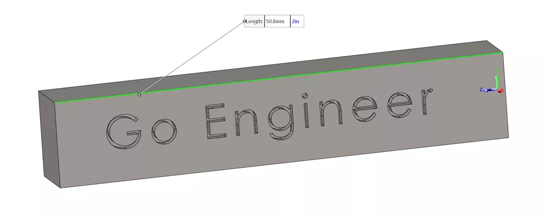
(Figure 1.12)
To predict the resultant “displacement” of our part, we can simply rewrite this as:
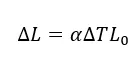
(Figure 1.13)
Now, if we apply this equation to our given variables, we can write this as:
ΔL = (1.8 * 10 -5 K -1)(100°C - 25°C)(50.8mm) = 0.068 m
(Figure 1.14)
We will compare this resultant expanded length to our simulation next.
Steady State Thermal Analysis
Once we have obtained our result from our Transient Thermal Stress analysis, let's confirm our result with a non-time dependent study.
Just like we did above, we will make a new Thermal study. Luckily, we do not need to change any of the study properties since a thermal analysis is static by default.
Going into the Thermal Loads data type, we can select the solid body that we will apply our 100°C load to.
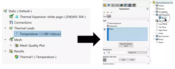
(Figure 2)
We will run this study and load the thermal properties into a static stress analysis, just like before. Remember we are selecting the Solid Body of our model. This ensures we apply our thermal load to the entire model rather than the outside faces.
This method is also recommended for non-uniform temperatures being applied to the model.
Thermal Static Analysis
We will follow the same procedure as we did for the Transient analysis > Static Stress analysis. We will also open the static stress analysis study properties and select Static to recall the thermal results of our non-time dependent thermal analysis (2.1). This setup is quite like before though we will neither select Transient nor a time step for our study.

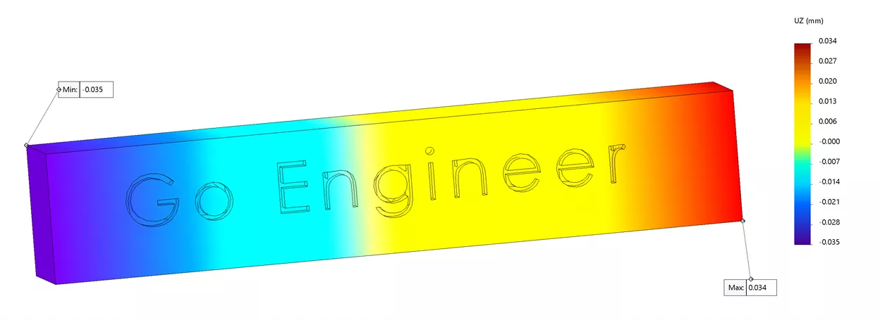
(Figure 2.1)
After we set up the Static analysis (with the thermal loads of our Static Thermal Analysis), we can review the results.
First, I was able to get a total displacement (from the center of my model) of 0.069mm, only 0.001mm off with only a 1.47% error.
Conclusion
Luckily all I had to suggest to the customer was that they run the study as I did here. Although their model and results were different than mine, the method still applies. One could also simply run this analysis in a Thermal Static analysis. I hope this cleared up any confusion on how to run a thermal expansion analysis for your part! Check out more SOLIDWORKS Simulation articles below.
More SOLIDWORKS Simulation Analysis Tutorials
7 Steps to Perform a Fatigue Analysis in SOLIDWORKS Simulation
Performing a Thermal Stress Analysis in SOLIDWORKS Simulation
How to Perform a Drop Test in SOLIDWORKS Simulation
Introduction to Structural Analysis
SOLIDWORKS Simulation Frequency Analysis Comparison Between FEA and Real Life

About John Nikoloff
John Nikoloff is a Simulation Specialist Application Engineer at GoEngineer based out of the Salt Lake City, Utah region. With his Applied Physics Bachelors, John joined the GoEngineer team in 2020 and has been creating content and supporting customers since completing his CSWA and CSWP certifications. His current proficiency is in teaching, where he can explain the functionality of the physics engines inside the FEAs covered by GoEngineer. Luckily, there are always new things to learn and build content for. Apart from immersing himself in the mathematics and physics of these engineering tools, John is a complete music nerd and enjoys writing music with his friends and band mates. When he is not busy practicing, he makes time to spend with his kitten or spending time with his friends.
Get our wide array of technical resources delivered right to your inbox.
Unsubscribe at any time.