Using Sheet Metal Bodies in SOLIDWORKS Simulation
The use of sheet metal bodies in SOLIDWORKS Simulation provides a streamlined study setup workflow. The nature of sheet metal geometry leads to the utilization of shell elements to represent their shape in a simulation study.
The use of solid elements is prohibitive due to the large aspect ratio difference between the span and thickness of sheet metal bodies. Their usage would lead to very large mesh size and corresponding computational effort. Shell elements allow for the creation of a mesh with high surface fidelity while limiting the required system resources needed for the calculation. This document will cover how sheet metal bodies can be used to simplify the creation of linear static analysis.
Model Creation
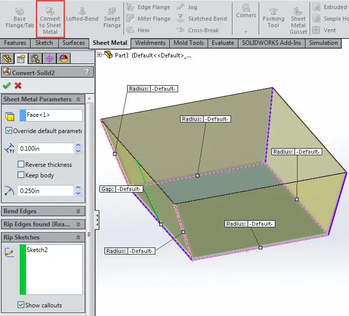
The streamlined study setup in SOLIDWORKS Simulation requires the geometry to be created using SOLIDWORKS sheet metal entities. This can be accomplished by creating a new model constructed with sheet metal features (base flange, edge flange, miter flange, etc.) or an existing solid body can be converted into a sheet metal body by using the “convert to sheet metal” and “insert bends” features. This allows for working with imported solid body geometry.
A planar surface is selected in the convert to sheet feature to represent the fixed surface for the flat pattern. Model edges can be selected to specify where the bends will take place. The software will automatically rip appropriate edges so that the body can be flattened properly. A sketch can also be used to create a rip across a solid surface so that it can be unfolded.
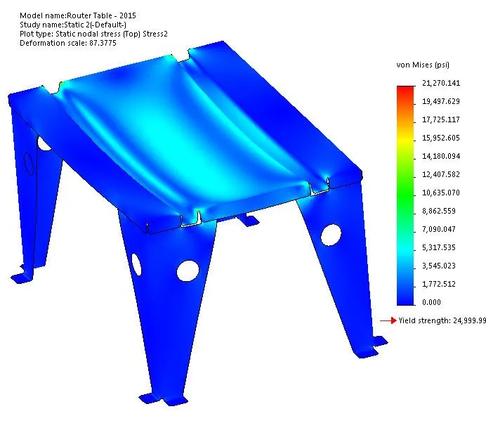
Linear Static Analysis
Shell Definition
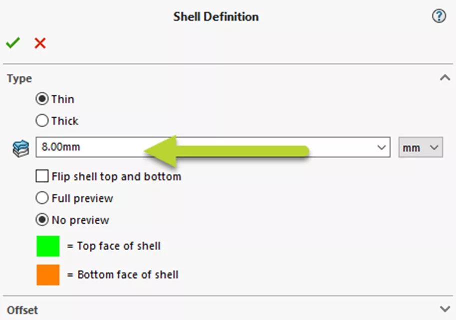
During the creation of a linear static analysis, sheet metal bodies are automatically converted into shell entities. A surface body is created at the mid-plane of each sheet metal body for utilization in the shell definition and the offset condition is set to middle surface. The shell thickness is tied to the thickness defined for the sheet metal body and cannot be manually changed. Changing the thickness of the sheet metal body at the part modeling level will update the shell definition. This process ensures that the resulting shell mesh will always match the underlying solid geometry during the calculation.
Contact Conditions
Sheet metal bodies simplify the setup of contact conditions by utilizing the automatic bonding created by the global contact condition. The following scenarios make use of automatic bonding:
- A face to face coincident contact between sheet metal bodies
- Edges of a shell body which are in direct contact with a sheet metal surface
- A face to face coincident contact between a solid surface and a sheet metal surface
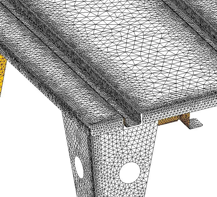
The bonding is applied to the mid-surface of the shell mesh created for the sheet metal body. This results in an incompatible mesh being created due to the physical gap between the shell element mid-surface and the interfacing entities. This can lead to an inconsistent bonded region. Refining the mesh in the contact region will result in a more complete description of the bonded contact. The finer mesh allows for more elements and nodes to participate in the incompatible bonding algorithm. When bonding a shell edge to a sheet metal surface, the software rigidly connects each node point along the shell’s edge to the nearest element’s face on the sheet metal body. To improve accuracy, the element size on the sheet metal surface should be equal to the shell thickness.
The global no-penetration contact condition does not apply to contact regions involving sheet metal bodies meshed with shell elements. Local no penetration contact sets need to be created and will work for the following scenarios:
- Contact between the exterior surfaces of sheet metal bodies
- Contact between edges of a shell body and a sheet metal surface
- Contact between a solid surface and a sheet metal surface
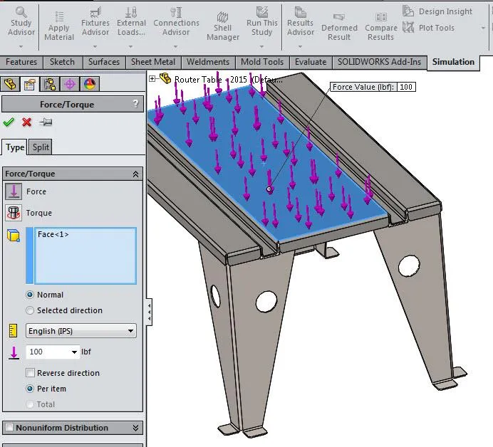
Fixtures and Loads
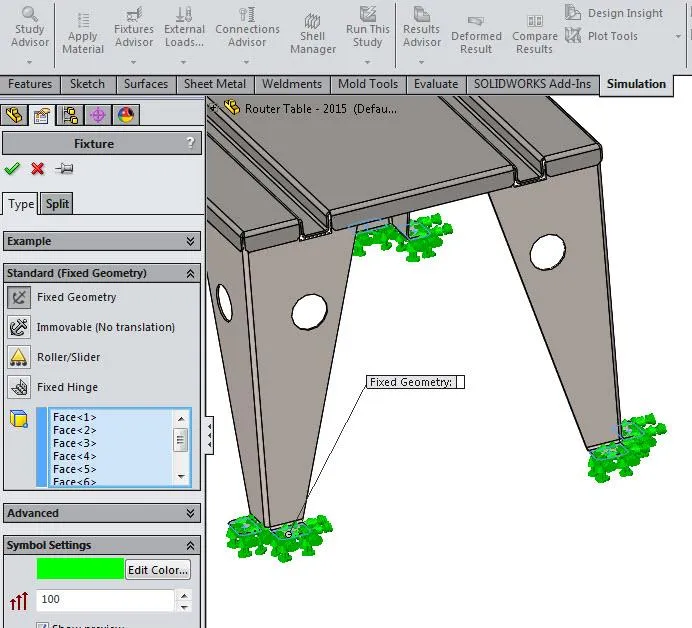
Using sheet metal bodies simplifies the workflow of setting up boundary conditions since fixtures and loads can be applied to any edge or surface on a sheet metal body. A fixture or load that is applied to the exterior surface of a sheet metal body is projected onto the mid-surface of the shell mesh created for the sheet metal body. A boundary condition applied to the thickness surface of a sheet metal body is projected onto the edge of the mid-surface shell mesh.
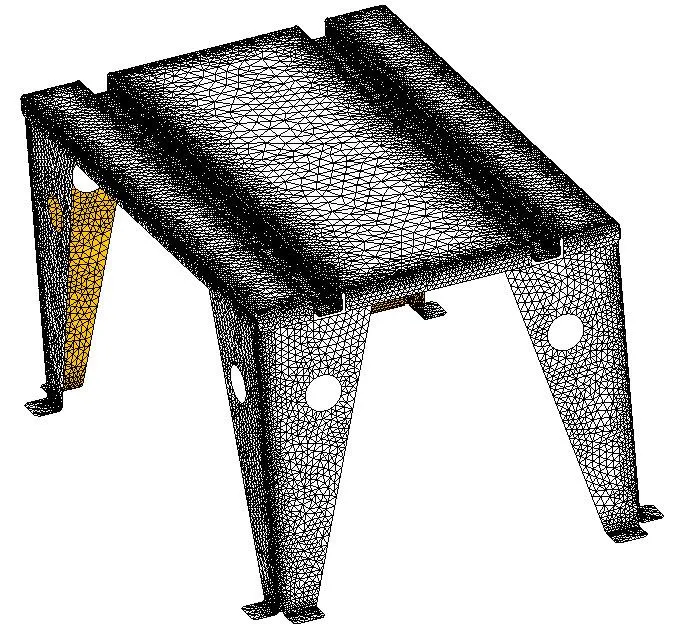
Meshing
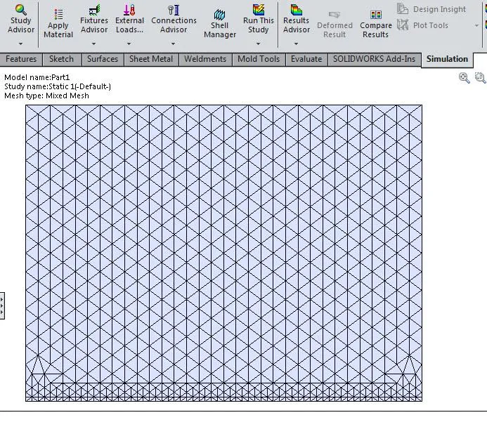
Meshing sheet metal bodies with shell elements greatly reduces the overall size of the mesh. Shell elements only mesh the exterior surfaces of sheet metal geometry and take into account the thickness during the calculation. The number of elements and nodes in the mathematical model is dramatically reduced by not having to mesh the volume of a sheet metal body. This limits the number of degrees of freedom in the calculation resulting in greater computational efficiency.
Benefits
- Simplifies the analysis setup when shell elements are needed due to system and time constraints
- A large reduction in the overall mesh size while maintaining a good surface mesh fidelity, which lowers the system memory requirements and results in a faster solution
- Multiple what-if scenarios can be run to explore the design space in a shorter amount of time due to the reduced computational effort
I hope you found this article about the benefits of using sheet metal bodies in SOLIDWORKS Simulation helpful. For more information, check out the links below.
More SOLIDWORKS SIMULATION Articles
Backspin in Important to Your Basketball Free Throw! A SOLIDWORKS Simulation Study
SOLIDWORKS Simulation Tips: No Penetration Contact Set Setup
A Guide for Using Bearing Connectors in SOLIDWORKS Simulation
SOLIDWORKS Simulation Videos
![]() Fixtures Better Practices - Simulation Tutorial
Fixtures Better Practices - Simulation Tutorial
![]()
About GoEngineer
GoEngineer delivers software, technology, and expertise that enable companies to unlock design innovation and deliver better products faster. With more than 40 years of experience and tens of thousands of customers in high tech, medical, machine design, energy and other industries, GoEngineer provides best-in-class design solutions from SOLIDWORKS CAD, Stratasys 3D printing, Creaform & Artec 3D scanning, CAMWorks, PLM, and more
Get our wide array of technical resources delivered right to your inbox.
Unsubscribe at any time.