Using Shell Elements in SOLIDWORKS Simulation for Frames
In this walkthrough, we go over how to modify CAD geometry for Shell Elements, focusing on Framework in SOLIDWORKS Simulation.
Shelling Framework
When using framework, it is often part of a larger assembly; and trying to mesh a large assembly can bring your PC to its knees with all the required processing power.
So instead, let's focus on a singular beam.
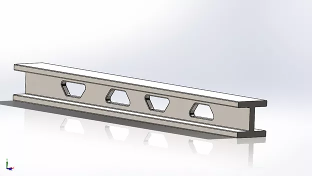
In some instances, beam functionality can be used however, if the cross-section is not continuous, you will have errors. This guide will help walk you through getting around when the beams may not be continuous.
First, you will want to start with the process of CAD Conditioning or making three surface bodies to accept the shell elements.
In the process of learning these techniques, we will over cover Offset Surfaces, Extend Surfaces, and Split Line.
Before getting started, back up the part in case it’s needed.
With the backup created, we'll first make a new configuration; specifically an FEA configuration of the part. This way, the part can be manipulated without creating issues within the assembly downstream.
Once the FEA Configuration is created, we can edit the part to suit our needs.
If there are any fillets or chamfers, suppress them to better help with the meshing of the part.
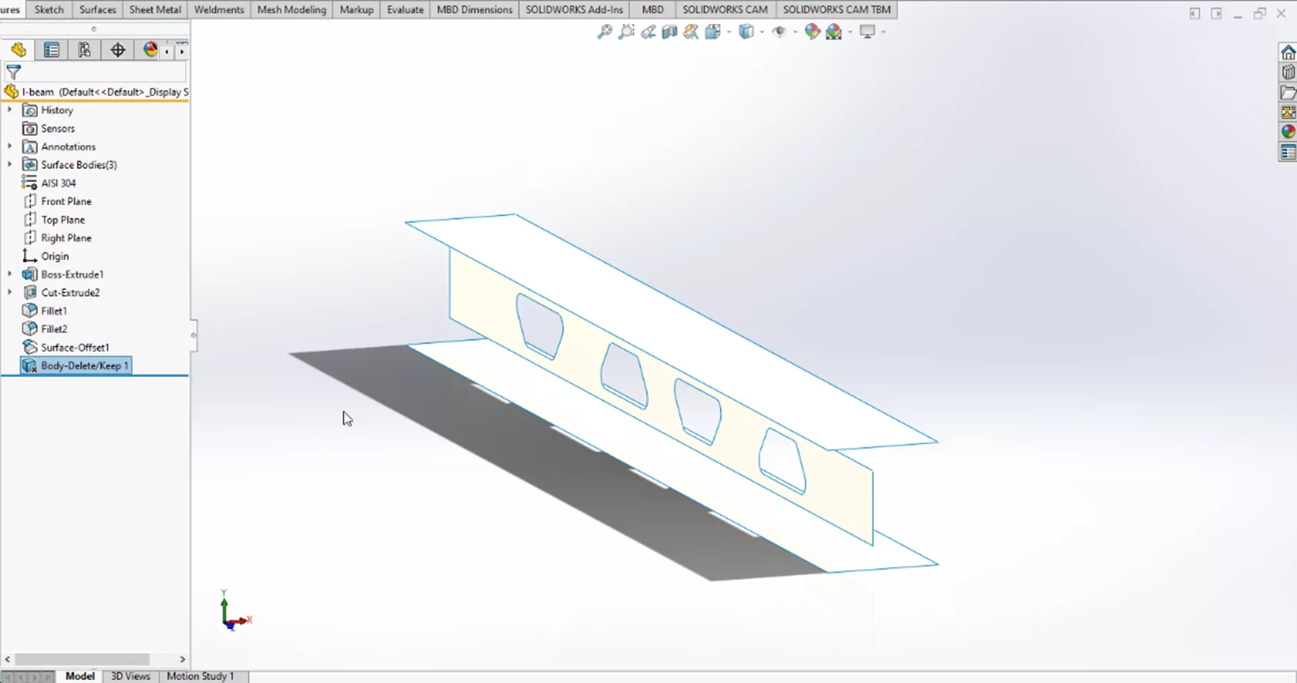
With the fillets/chamfers suppressed, we will want to offset the top, bottom, and web surfaces by half the thickness of the part. Doing this will create the surface bodies we will need to continue with the Shell Element.
Once the offsets have been created, Delete Body can be used to remove the solid body of the beam to prevent confusion when meshing and running the simulation.
And, because we made an FEA configuration, we won't make changes to the part downstream in the assembly.
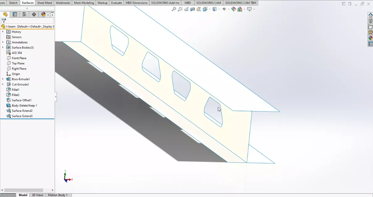
When creating new surface bodies, gaps may appear that will need to be fixed. Use Surfacing tools, specifically Surface Extend, to extend the surfaces of the web to join the top and bottom surface bodies.
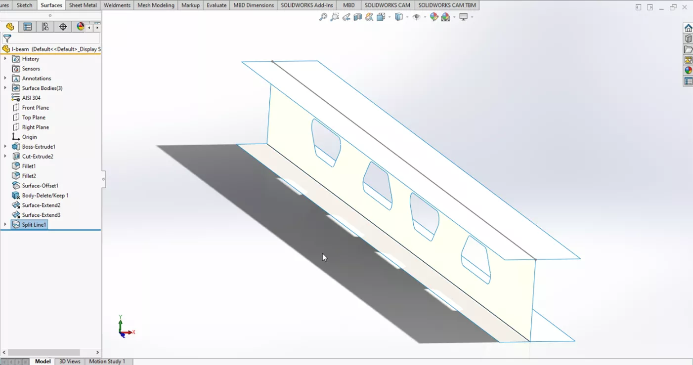
In order to get a good mesh, convert the edges of the body of the beam into a split line.
To do this, highlight the edges of the beam surface body, then select Convert Entities.
There will be a black line shape where the edge of the body of the surface meets the upper and lower surface bodies.
With the newly created line, we can use a Split Line command and use the top and bottom surface bodies along with the newly created line to make the Split Line.
With the preliminary model working out of the way, we can carry on preparing our Simulation.
Setting up the simulation
With the surface bodies all set up from our prior steps, we can create a study. We will use the Static default, name the study, then green check.
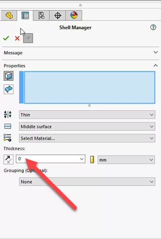
Because these parts are surface bodies, we need to define the actual thickness using the Shell tool.
Select the Thin surface and then use an edge to give the thickness a direction and set the thickness. For this example, we will use 0.394.
At this point we should also set up material for the part, in this instance we will use Alloy Steel.
Now that the surface bodies have a thickness to them, we can run the Mesh command using the default settings within the Mesh Control Panel. Once the mesh is complete, we can move on to the next step.
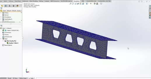
With the thickness added and a mesh applied, you can now run the simulation.
I hope this guide has helped guide you in creating your Shell Element for Frames. If you would like to see a video on this, you can view it here.
More SOLIDWORKS Simulation Tutorials
Free SOLIDWORKS Simulation Tutorials
Analyzing SOLIDWORKS Simulation Drop Tests
SOLIDWORKS Motion Analysis Motor Torque & Power
SOLIDWORKS Simulation Natural Frequencies, Mode Shapes, and Vibration Explained
How to Set Up a Thermal Study in SOLIDWORKS Simulation Professional

About Krystal Petersen
Krystal Petersen is a SOLIDWORKS Technical Support Engineer based out of Auburn Hills, Michigan. Krystal studied Product Engineering at Oakland Community College and has earned her CSWA and CSWP Certifications. She joined the VAR channel in 2015 with DASI (now GoEngineer). Krystal is a huge fan of Star Wars and likes to spend her off time fishing and camping.
Get our wide array of technical resources delivered right to your inbox.
Unsubscribe at any time.