SOLIDWORKS Electrical Drawing Styles Setup
Table of Contents
When working in SOLIDWORKS Electrical, setting up a Project Template is an essential part of the process, and setting it up effectively will save you a significant amount of time later when creating Electrical Projects. A tool that is often overlooked when setting up templates is the Drawing Styles Configuration.
With the Drawing Style Configuration tool, you can set up and save your company’s standard Layers, Linetypes, Text styles, and Leader styles in one location. This guide explains how to access this tool and what to expect when setting it up for your templates.
Drawing Style Configuration
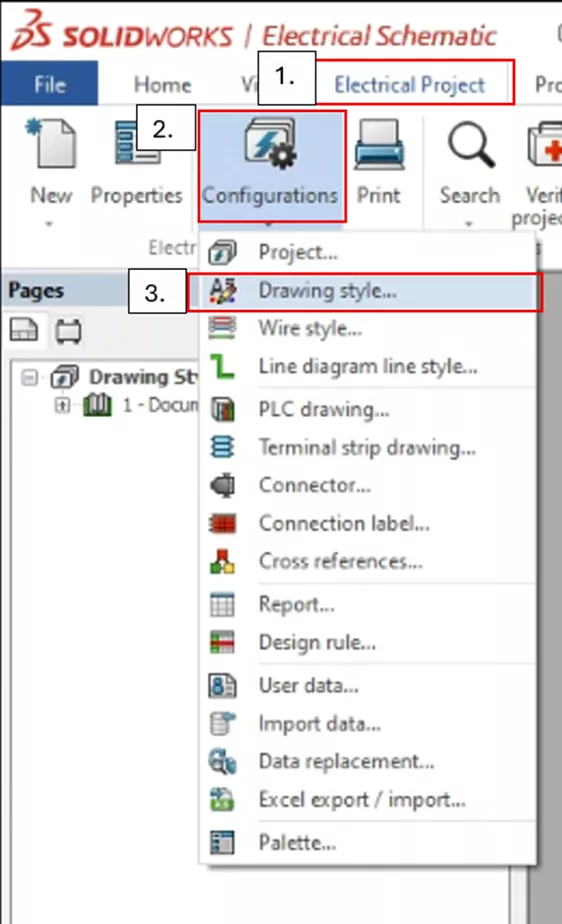
Under the Electrical Project tab, select the down arrow under Configurations and click Drawing styles...
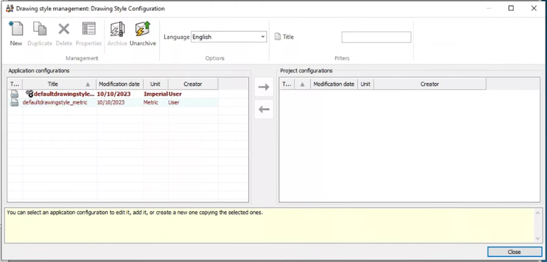
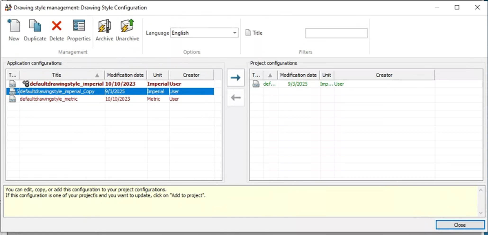
This will open the Drawing Style Manager. From here, you can see several commands and two sets of lists: Application configurations and Project configurations.
The Application configurations contain any custom-made drawing styles or the two default configurations. This is the main list of drawing styles, and can be accessed from any project. The Project configurations are drawing styles that have been added to the current project.
This command lets you control the Application Configurations. First, there is the option to create a new configuration from scratch, adding exactly what you want for your projects.
Another option is to create a duplicate of the currently selected Application Configuration.
The third option is to delete, which, as stated, allows you to delete the currently selected configuration.
The properties command lets you modify the currently selected configuration.
The ability to archive and unarchive configurations is also available. This process lets you save and share configurations, much like an Environment archive.
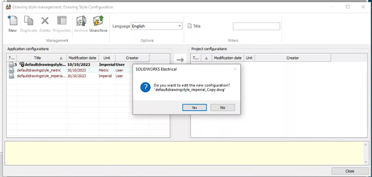
Now that we have a handle on the commands we can use, let's go over an example and start by duplicating the Defaultdrawingstyle_imperial configuration.
A prompt will appear with the option to edit the new configuration. For this example, we'll select Yes.
Editing Drawing Style
Here, a new menu, named Edit drawing style: IMPERIAL, includes several tabs. Starting with the Layer tab, you can see the default layers and their settings.
Layer
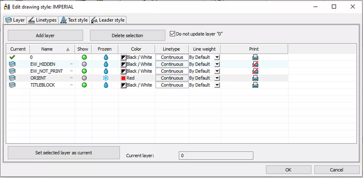
The Current column lets you control which layer is the current layer. Select a layer and click the Set selected layer as current button in the bottom left corner.
In the Name column, you can change the name of the current layers and set the name of new layers.
The next column (Show) indicates whether a layer is set to show (green circle) or is hidden (grey circle). Hidden items will not be printed.
The Frozen column is visually similar to the show column. If we were looking to improve performance, using the show and hide column is the better option.
The next three columns pertain to how items on a layer will appear, such as color, line type, and weight.
Lastly, the Print column determines whether items on this layer will show when you print the drawing.
Linetypes
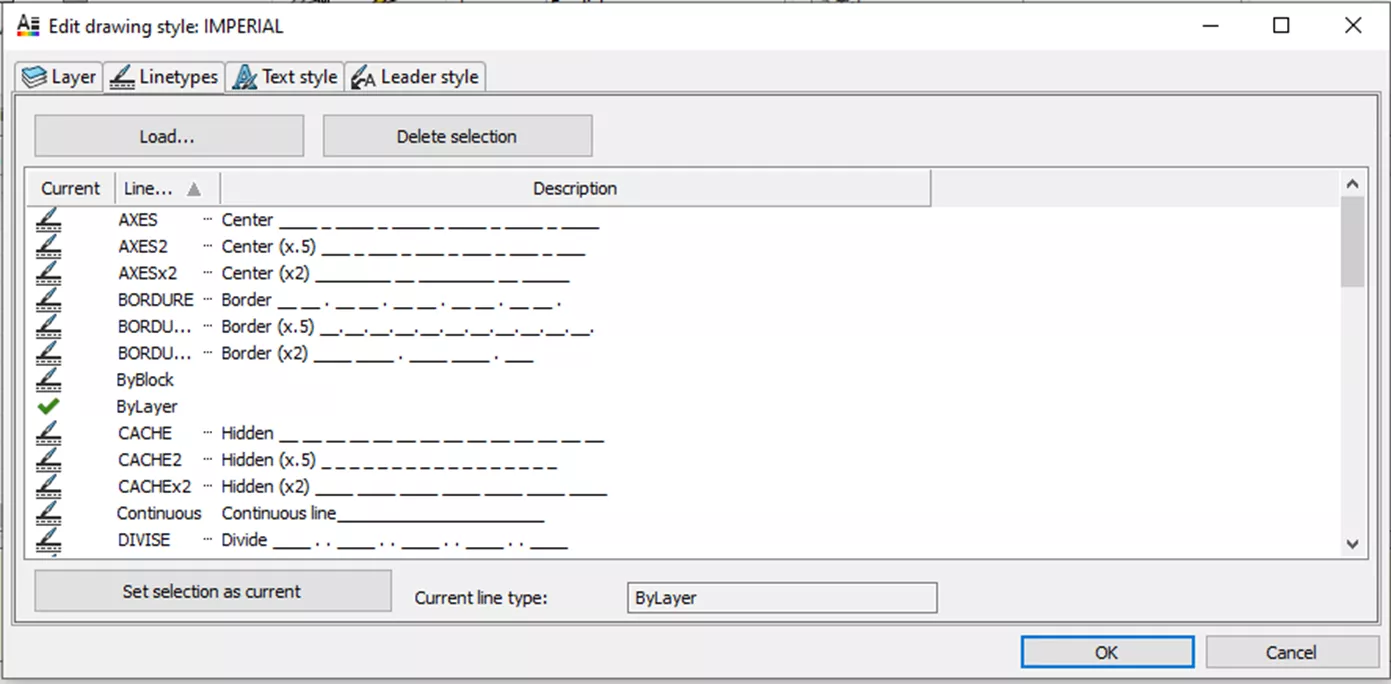
The Linetypes tab contains various line styles that can be accessed in the drawings for wires, cables, etc. In this tab, you can load new line styles from XLIN files or delete the current selection. You can also select the current line style to be the currently active line style in your project.
Text Style
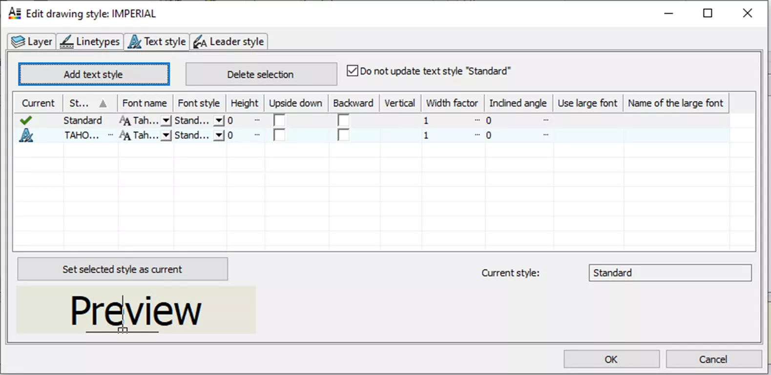
In the Text style tab, you can add and delete text styles and set the current selection as active. Unlike the Linetypes tab, there is plenty of control over these styles, for example, changing the font and its parameters.
Leader Style
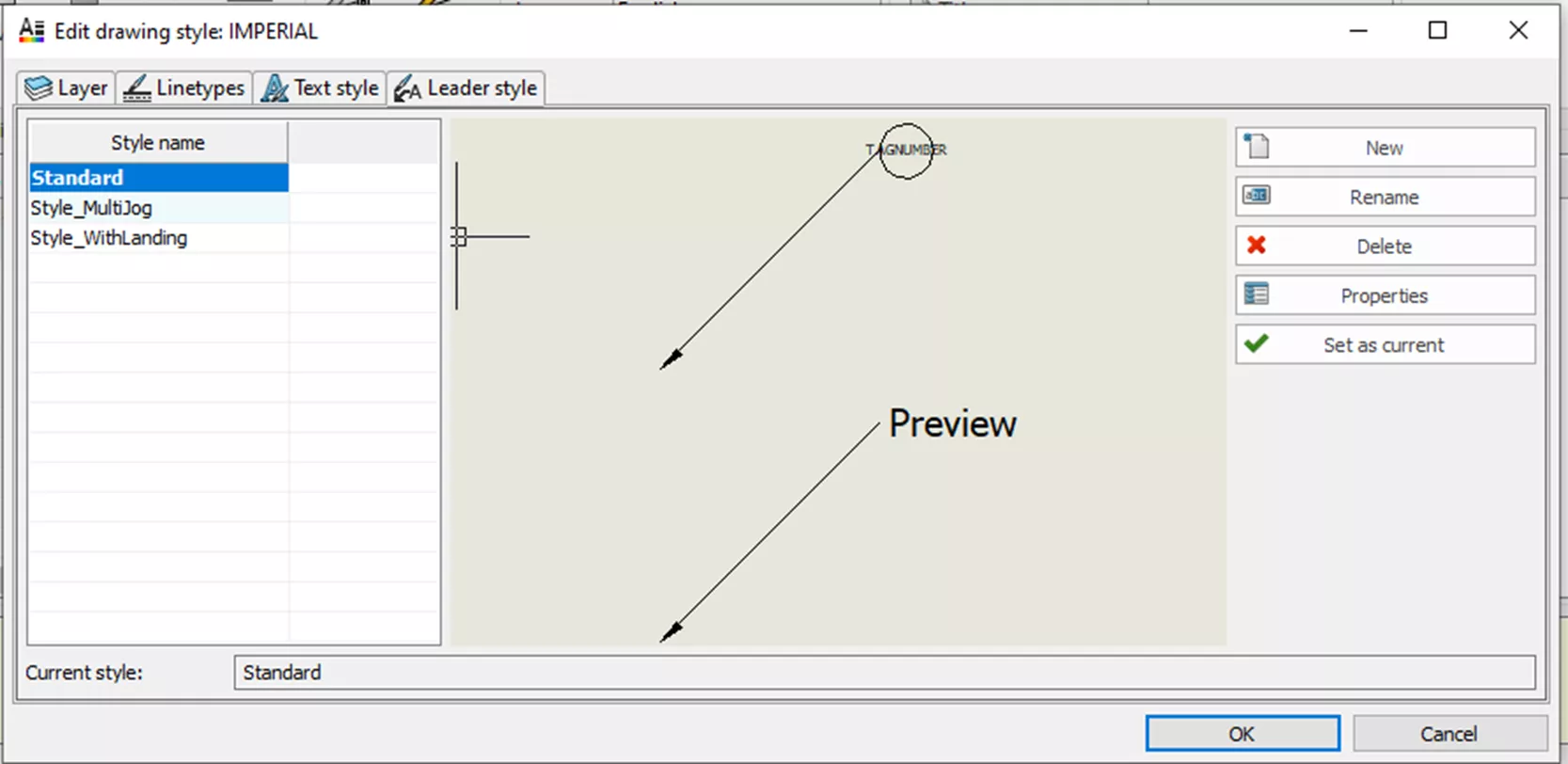
The Leader Styles tab contains a list of your existing Leaders, a preview, and commands.
These commands are similar to the commands we have seen before.
- New creates a new leader style. This leader style starts off as a copy of the selected leader that can then be modified.
- Rename allows you to rename the selected leader.
- Delete allows you to delete the selected leader style.
- Properties allow you to modify the settings of the selected leader.
- Set as current sets the selected Leader Style as active.
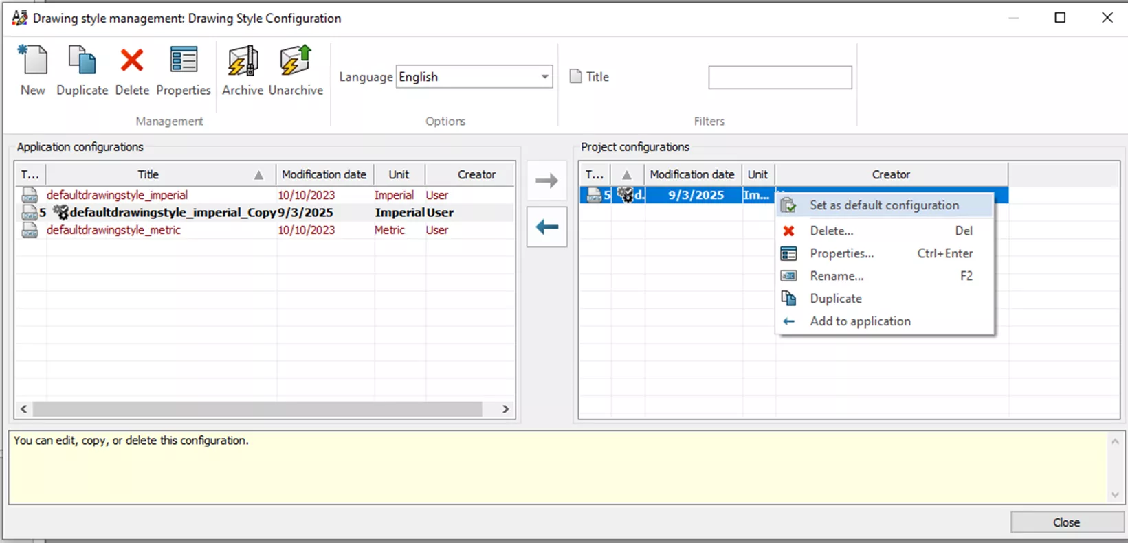
Once all modifications have been made to your Drawing Style, hit OK. This returns you to the Drawing Style Management menu. With the new Drawing Style selected, select the right arrow to add your Drawing Style to the Project.
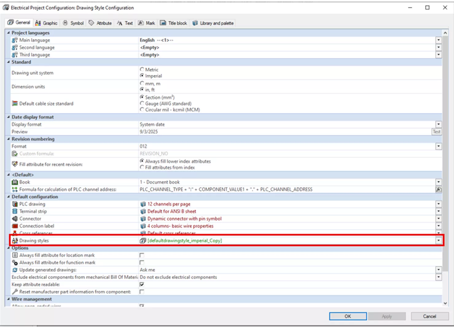
Right-click on the Project Configuration and select Set as default configuration. This replaces the current drawing style in the Configurations Project Menu.
Now that Drawing Style is set, you can proceed with setting up and saving your Project Template.
Want to learn more about SOLIDWORKS Electrical? Check out the articles listed below. Additionally, join the GoEngineer Community to create forum posts, enter design contests, and answer questions from other SOLIDWORKS users.
Related Articles
Replace Data within a SOLIDWORKS Electrical Project
SOLIDWORKS Electrical Custom Library Design Rule Check
SOLIDWORKS Electrical Schematic: Displaying Alpha Numeric Rows & Columns
Adding PLC Drawing Configurations to SOLIDWORKS Electrical Projects
SOLIDWORKS Electrical Save Manufacturer Part Info in a Symbol
![]()
About Nathen Blas
Nathen Blas is a SOLIDWORKS Technical Support Engineer based out of our Headquarters in Salt Lake City, Utah. He earned his Bachelor’s degree in Mechanical Engineering at the University of Utah in 2018 and joined the GoEngineer family that same year.
Get our wide array of technical resources delivered right to your inbox.
Unsubscribe at any time.