3D Printed Drone Racing Frame: Engineering & Design
Welcome to part two of my 3D printed drone design adventure. If you haven’t had a chance, now is the time to check out part one here: Drone Racing Meets 3D Printing.
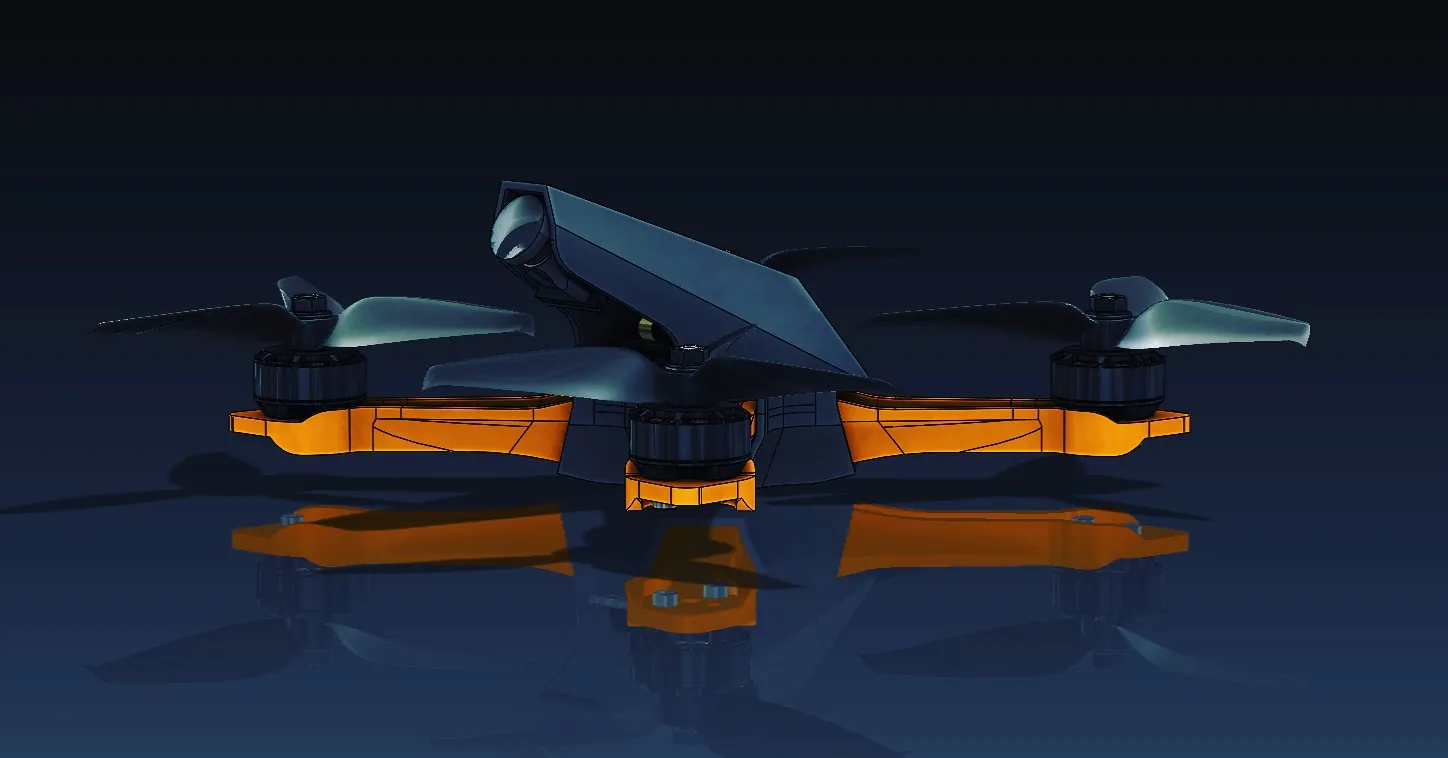
For a while now, I have been designing a drone frame that is to be 3D printed, and that will be able to handle the abuse that comes with first-person view (FPV) drone racing. The drone needs to be tough enough not to break into pieces if I come in contact with racetrack obstacles or “gates”.
Related Article: A Modern Take on a Classic: 3D Printed Fender Telecaster
It also needs to be strong enough to not break from high G-forces on high acceleration or sharp turns and light enough to maximize agility and performance. It needs to be rigid enough to minimize mechanical noise, slim enough to minimize drag, simple enough to be 3D printable by most, cool enough to interest people into the hobby, inexpensive enough, efficient enough, fast enough… (sigh)… You get the idea, we all want our own pet project to be the BEST!
Engineering and Design
I have been focusing on applying my engineering thought to my design of the drone frame. Consequently, I have gone through five iterations of the frame now. I think I found what I am looking for – or so I said the last four iterations.
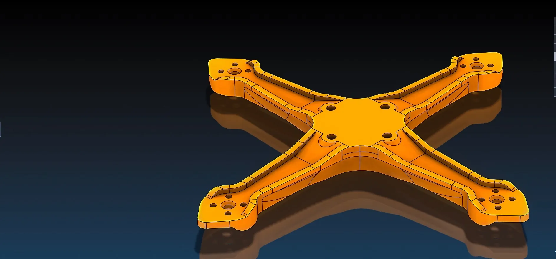
Using SOLIDWORKS Simulation I came to find an area that would be prone to fracture on small impact for each of the arms. I then decided to include a “raised perimeter” along the arms making the arms be more of a sideways I-Beam (see image below).
Related Article: Full Metal Iron Man Helmet Project
Compressive stress concentrations are now focused along these raised perimeters which 3D printed Stratasys Polycarbonate material can handle. I am glad that I have been changing my mind and kept correcting design issues while the drone was still in SOLIDWORKS. It is way better to find a design issue virtually than on the track.
Applying SOLIDWORKS Simulation
Motivated by the changes I was able to make after discovering them through SOLIDWORKS Simulation, I decided to continue my search for design issues. Specifically, I wanted to know more about the behavior of the drone frame under dynamic loading. Unnecessary vibrations, also called mechanical noise, are a really bad thing for a quadcopter that depends on sensors to function.
You may remember from childhood cartoons, a character singing very loud and hitting a specific note which shatters glass around the singer… Those notes are resonant frequencies of the glass.
Related Article: 3D Printed Trim Panel for Custom Shifters
For my drone, the singer is the motors – they provide the vibrations. The frame is the glass from the cartoon example. Although the frame will not shatter with motor vibrations, it will vibrate more vigorously at those resonant frequencies. I need to know where they are in the range of the motor’s minimum and maximum RPM. Programmatically, I can then attenuate or “lower the volume” of the problematic resonant frequencies in the firmware of the flight controller board so that the sensors function well.
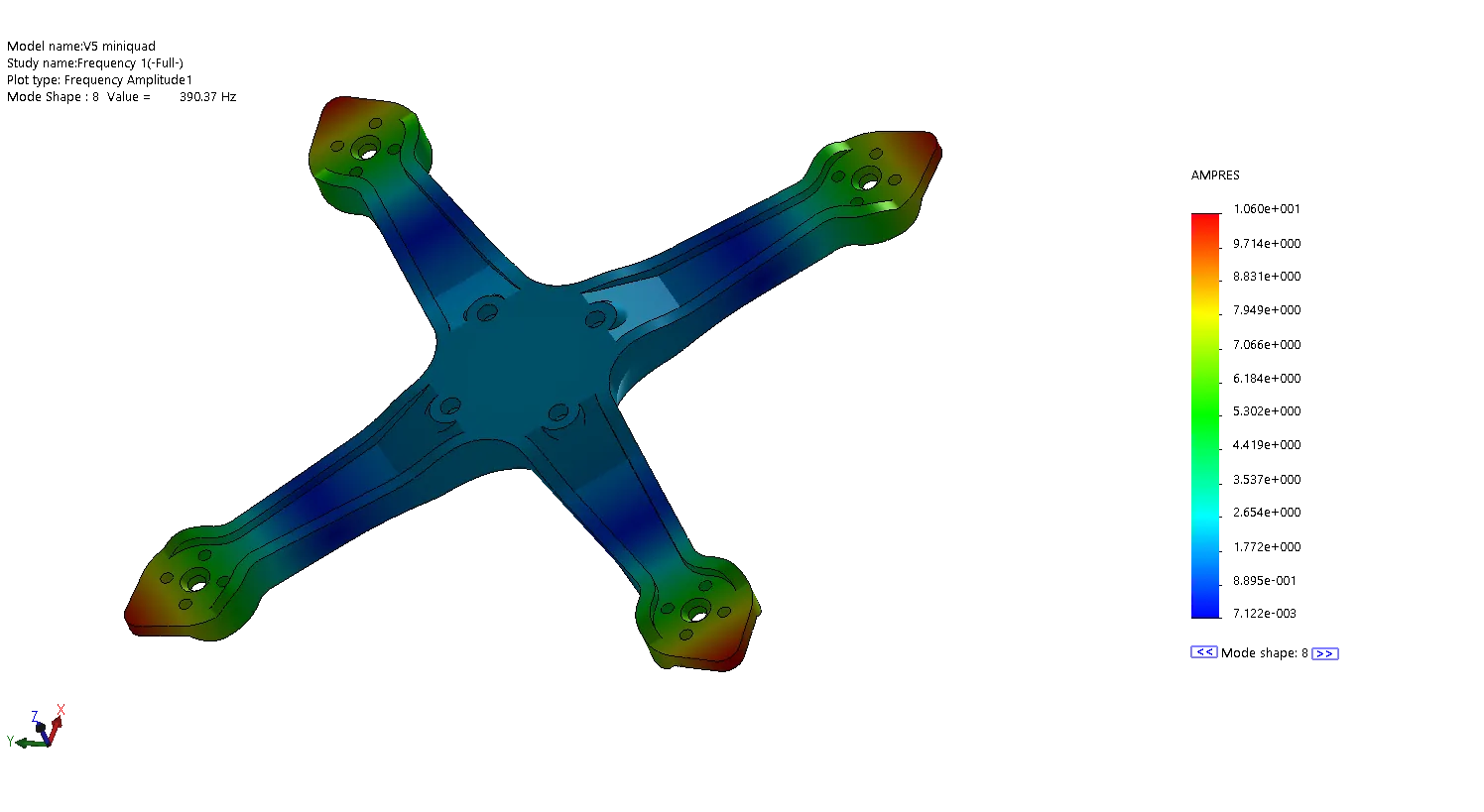
Running a Frequency Study
I used SOLIDWORKS Simulation again to run a frequency study. I found two resonant frequencies within the motor RPM range. One at 314.89 Hertz and another at 390.37 Hertz. Now some math (no worries it's easy). I’ll spare you the easy math, but these are 18893.4 RPM and 23422.2 RPM respectively. These values are well within the max RPM of the motors I chose that can spin up to 30,000 RPM at full throttle. I will now update the firmware to attenuate these frequencies.
Related Article: Frequency Study Plot with SOLIDWORKS Simulation
Next, I will focus on getting this drone 3D printed using our Stratasys 3D printers. I am sure I will learn a lot about the behavior of the frame at different printer settings. Stay tuned!

About Francisco Guzman
Francisco Guzman is the PDM Technical Support Lead at GoEngineer, and is pursuing his degree in mechanical engineering at the University of Utah. In addition to providing guidance and support to SOLIDWORKS and SOLIDWORKS PDM customers, Francisco also provides support for DriveWorks design automation. He won the world-wide DriveWorks reseller CPD contest as the best DriveWorks AE for 2015. For fun, he designs, 3D-Prints, builds and races custom first-person-view (FPV) racing drone frames.
Get our wide array of technical resources delivered right to your inbox.
Unsubscribe at any time.