5 Steps to Take Before Every SOLIDWORKS Flow Simulation Analysis
It does not matter whether your SOLIDWORKS Flow Simulation analysis is complex or simple, if you make it a habit to follow the five quick and easy steps outlined in this document, you will possibly save yourself hours of headache downstream after you have already spent hours setting up your Flow Simulation Study.
You now choose to mesh/run your SOLIDWORKS Flow Simulation analysis, but the solver fails, and you now need to go back and investigate what is wrong with your model. All of these steps are equally important and all need to be performed, but not in any specific order.
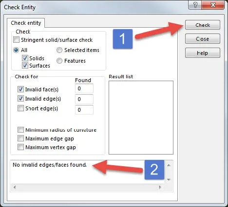
1. Check Entity
If you go to Tools>Check you can pull up the Check Entity Command Manager where you can specify what type of invalid geometry you would like to check for in your part or assembly. Press the Check button to check your model's geometry. Any invalid geometry will be shown in the bottom box of this CommandManager. Now you know where to go to fix your model's invalid geometries.
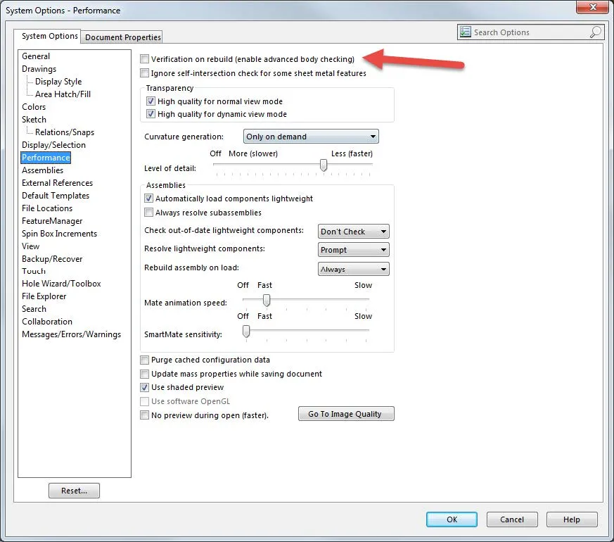
2. Force Rebuild with Verification on Rebuild (VOR) turned on
To activate this tool go to Tools>Options>System Options Tab>Performance>Verification on Rebuild checkbox. Make sure that this check box is checked and press OK. Now press CTRL – Q which is a global rebuild hotkey. The CTRL – Q hotkey will make sure that the whole model is rebuilt.
The active Verification on Rebuild option will make SOLIDWORKS checks every feature against all other existing faces and edges. Not just the adjacent faces and edges to that feature.
This operation may take a while depending on your file size and complexity, but it is worth it because you may find some features that fail which you now can go back and fix before you run your SOLIDWORKS Flow Simulation and it fails for reasons that you do not understand.
3. Interference Detection
This is a very useful tool that can be found in either the Evaluation tab on your CommandManager or under Tools>Interference Detection (at the assembly level).
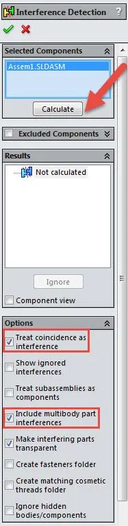
- First, click the Calculate button without checking any of the boxes in the options section. This will show all of the volumetric interferences in the results section. Volumetric interferences are spots in the assembly where two different parts overlap each other in space. SOLIDWORKS Flow Simulation will still try to calculate despite these volumetric interferences being present in the model, and sometimes it will converge and give a solution. Other times though it will fail. Even when it solves you will never know for sure if your solution is accurate. It is better all-around to find and fix these volumetric interferences before running a study.
- Next check the ‘Include multibody part interferences' and click Calculate. This will show any parts in your assembly with multibodies that are taking up space inside of each other. These interferences should be treated and fixed exactly like any volumetric interferences that you found in your model.
- Lastly, check the ‘Treat coincidence as interference’ box and click Calculate to show exactly where your assembly parts are touching wall to wall. This is especially important when running an internal study that must be air-tight to run. Make sure to check all your coincident parts to make sure that there are no parts of your assembly that should be coincident and are not, to keep your entire study airtight.
4. Check Geometry
This tool can be found by going to Tools>Flow Simulation>Tools<Check Geometry. Once this tool is open press the check button and under the results section, it will tell you whether the model has any invalid contacts, or is not air-tight.
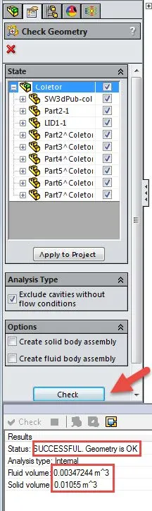
- If the model has any invalid contacts then it will not solve. Invalid contacts are points in assembly models where two different parts are touching each other and creating zero thickness geometry. Like a corner or point of a part touching another part. SOLIDWORKS Flow Simulation will not solve if there are any of these types of contact sets in the model.
- In the case of internal studies, SOLIDWORKS Flow Simulation will also not solve if the model is not air-tight so the Fluid volume and Solid volume in the results section should be greater than zero to show that the internal model is air-tight.
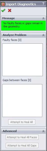
5. Import Diagnostics
The Import Diagnostics feature should be used on all imported part files (IGES, STEP, Parasolid, etc.). Sometimes when a part or assembly file is imported into SOLIDWORKS it can come in with faulty geometry such as faulty faces or gaps that will cause errors to appear in a Flow study if they are not healed before running the study.
The Import Diagnostics CommandManager can be told to ‘Attempt to Heal all Faces’ or ‘Attempt to Heal All Gaps’ or both simultaneously by clicking ‘Attempt to Heal All’. If there are any faces or gaps in the imported geometry that still cannot be healed by using this tool then you as the user will have to go in and manually fix whatever the problem areas are before running Flow Simulation on this imported part or assembly.
Expand Your SOLIDWORKS Flow Simulation Skillset
Customizing SOLIDWORKS Flow Simulation Feature Tree Categories
Different Pressures in SOLIDWORKS Flow Simulation
Backspin is Important to your Basketball Free Throw! A SOLIDWORKS Simulation Study

About Taran Packer
Taran is a SOLIDWORKS Simulation Technical Support Specialist at GoEngineer. He has a Bachelor’s degree in Biomedical Engineering from the University of Utah. Taran enjoys learning about different tools in SOLIDWORKS Simulation, Flow Simulation, and Plastics.
Get our wide array of technical resources delivered right to your inbox.
Unsubscribe at any time.