3DEXPERIENCE SIMULATION
Cutting-Edge CAE Made Accessible and Affordable
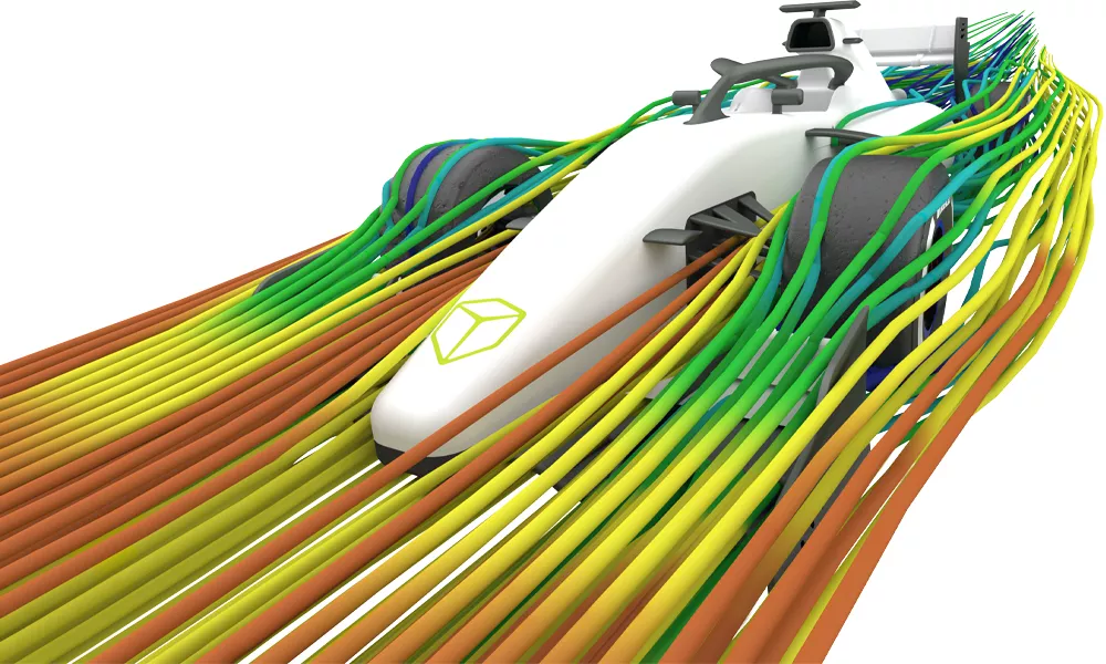
Top-of-the-Line SIMULATION Technology
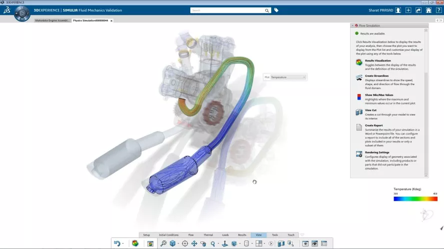
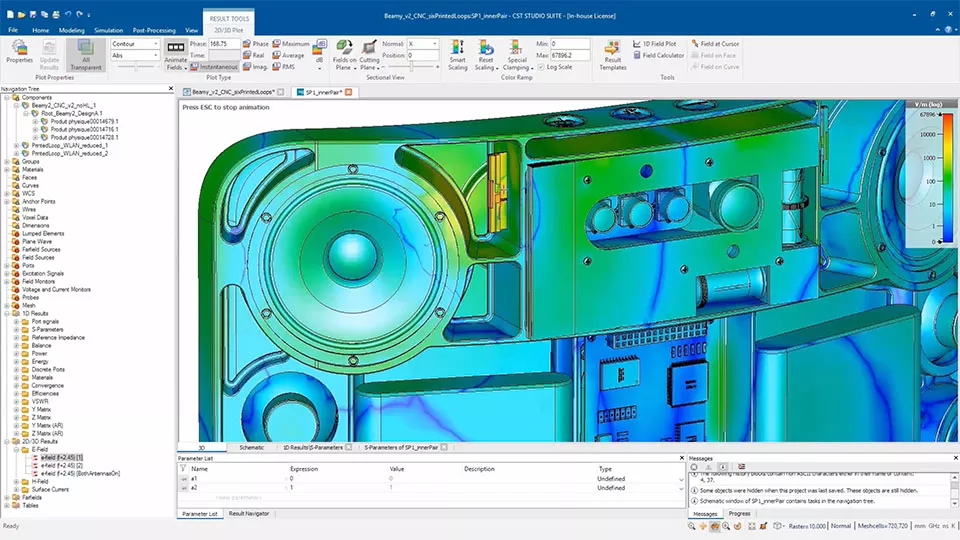
3DEXPERIENCE SIMULATION tools are powered by industry-leading FEA & CFD solvers like Abaqus. They give businesses a have-it-all approach to CAE:
- Comprehensive catalog of analysis capabilities
- Highly accurate simulation results
- Efficient handling of the largest assemblies
- Scalable computational resources
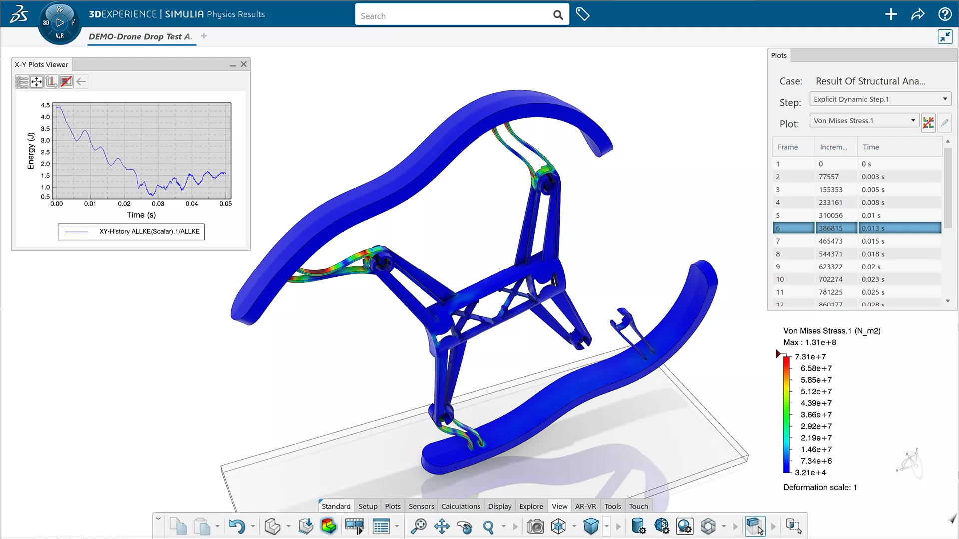
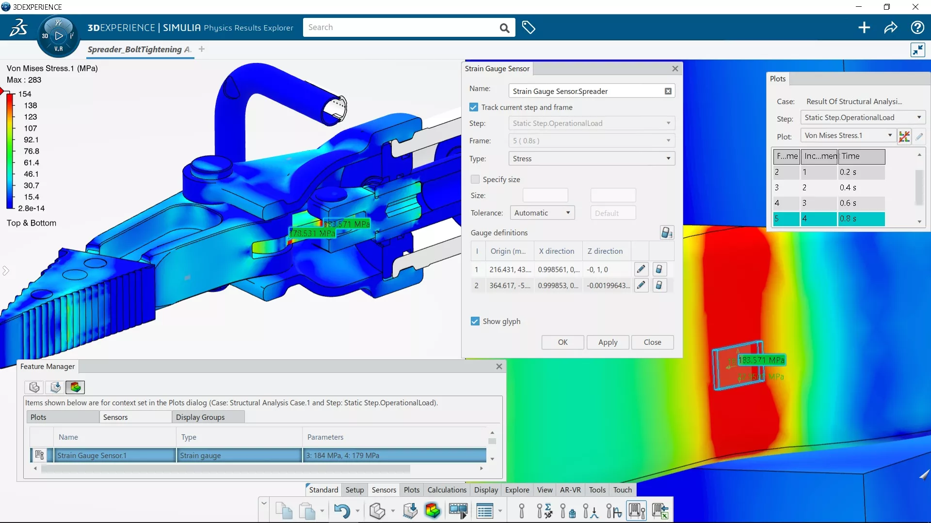
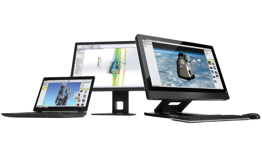
3DEXPERIENCE SIMULATION also introduces a new generation of CAE pre-/post-processors that are fully integrated into 3DEXPERIENCE's cloud PDM system. Simulation setup wizards, FE automation tools, and CAD associativity simplify and speed up the modeling process.
upcoming live demo events

Advanced Simulation Seminar Series
Join an Advanced Simulation Seminar in your city for an introduction to advanced designer-focused simulation which makes powerful FEA & CFD accessible to all SOLIDWORKS users.
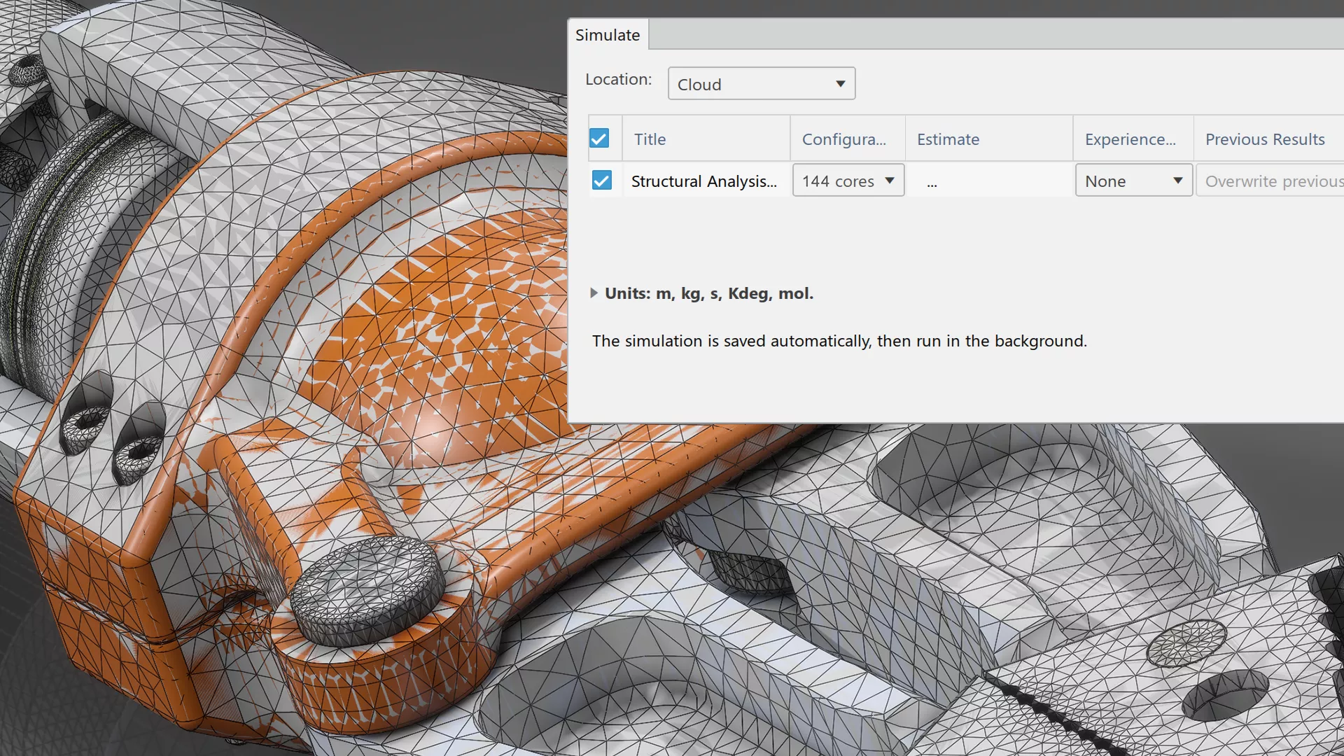
A New Cloud Computing Reality
3DEXPERIENCE SIMULATION offers on-premise and on-cloud computing options that can transform a CAE department:
- Keep your workstation free (or take it anywhere) by offloading the solve to the cloud.
- Compute the largest simulations you can imagine — affordably — with hundreds of CPU cores on-demand.
- Turn days of computation time into hours by solving your iterations and load cases concurrently on-cloud.
- Never research, purchase, and maintain an expensive simulation server again.
- Affordably introduce new FEA & CFD tools with 3DEXPERIENCE SIMULATION's universal licensing.
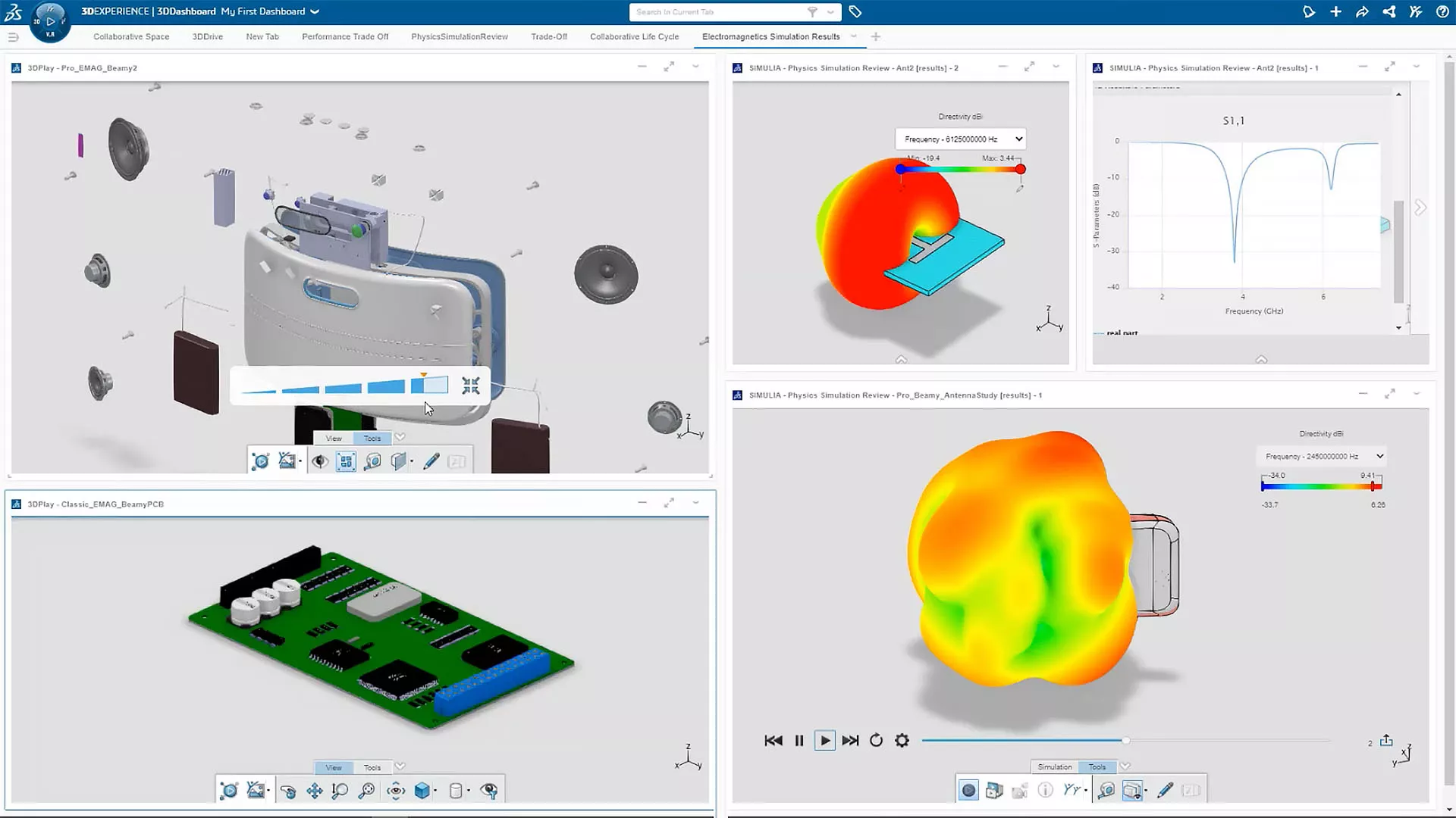
Streamlined Sim Collaboration
3DEXPERIENCE SIMULATION is part of a unified platform approach to product development software. It eliminates the data discontinuities and functional barriers that slow down the simulation phase of product development:
- Access your simulation tools and data from any internet-connected Windows machine.
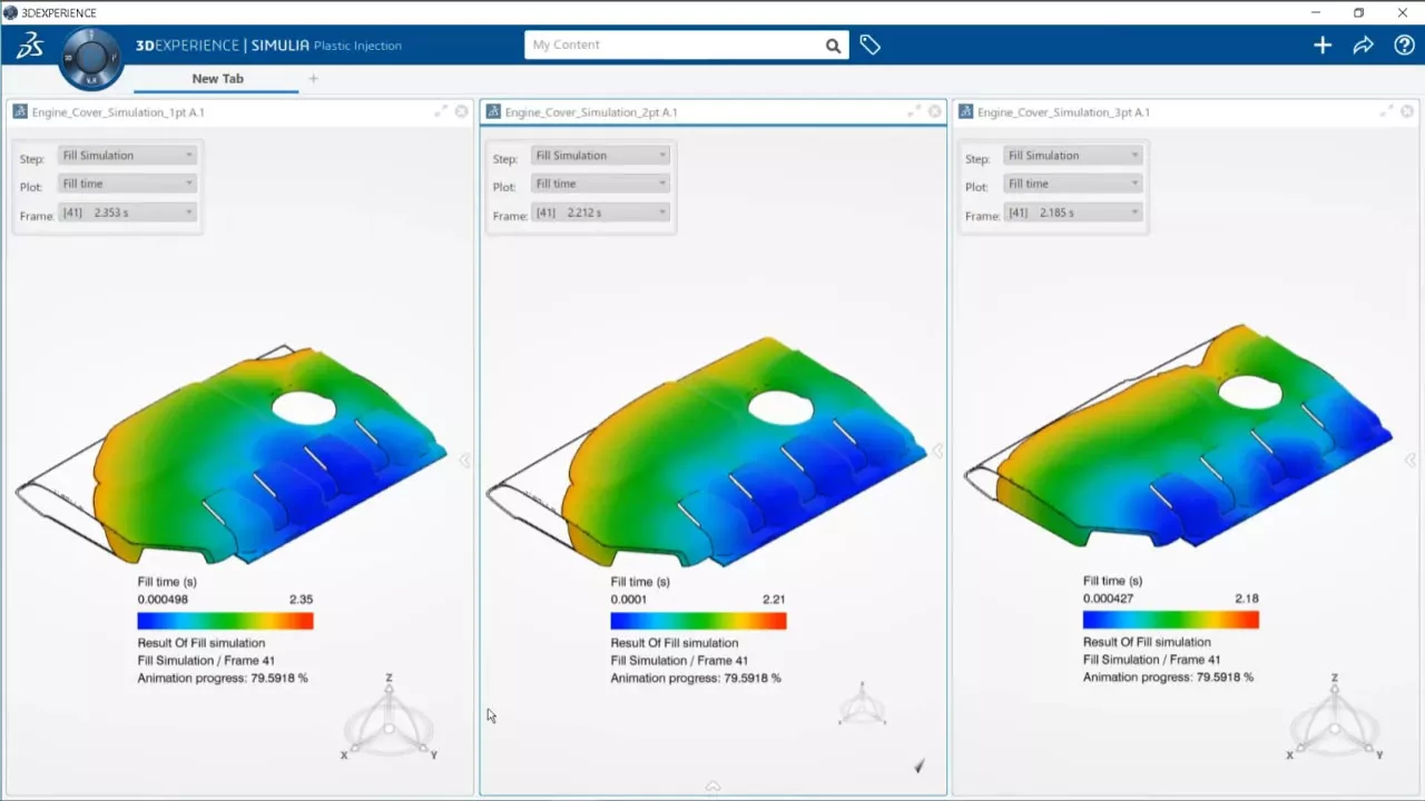
- Revision control analyses and compare results across design iterations using the browser-based data management system.
- Process design updates into new, complete FE models in just a few clicks.
- View and share simulation results on-cloud without having to download and upload large files.
The Engine That Powers MODSIM
The 3DEXPERIENCE SIMULATION portfolio is much more than standalone simulation tools. It powers MODSIM, a truly unified concurrent design and simulation process that will help you:
- Get to market faster
- Do less physical prototyping
- Lower development & manufacturing costs
- Confidently innovate on the razor's edge
- Fix problems early & inexpensively
3DEXPERIENCE Simulation Solutions


3DEXPERIENCE LEARNING
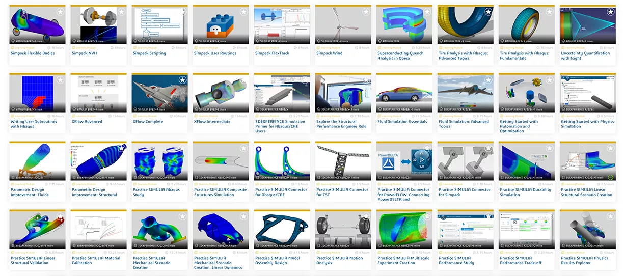
3DEXPERIENCE is powerful and transformative software, so learning to make the most of it isn’t trivial. Thankfully, Dassault Systèmes and GoEngineer provide plenty of resources on the path to proficiency:
- Official and custom-tailored classroom training
- Online training courses on the Learning Space
- GoEngineer’s quick-response technical support
- Extensive official documentation
- Dassault Systèmes Knowledge Base of supplemental materials, technical articles, and support tickets
- GoEngineer self-paced training
- GoEngineer simulation mentorship programs
- GoEngineer consultative methodology development
THE GOENGINEER CUSTOMER EXPERIENCE
- Support
- Training
- Extended Services
- Customer Portal & Community
- Unified Portfolio
Support
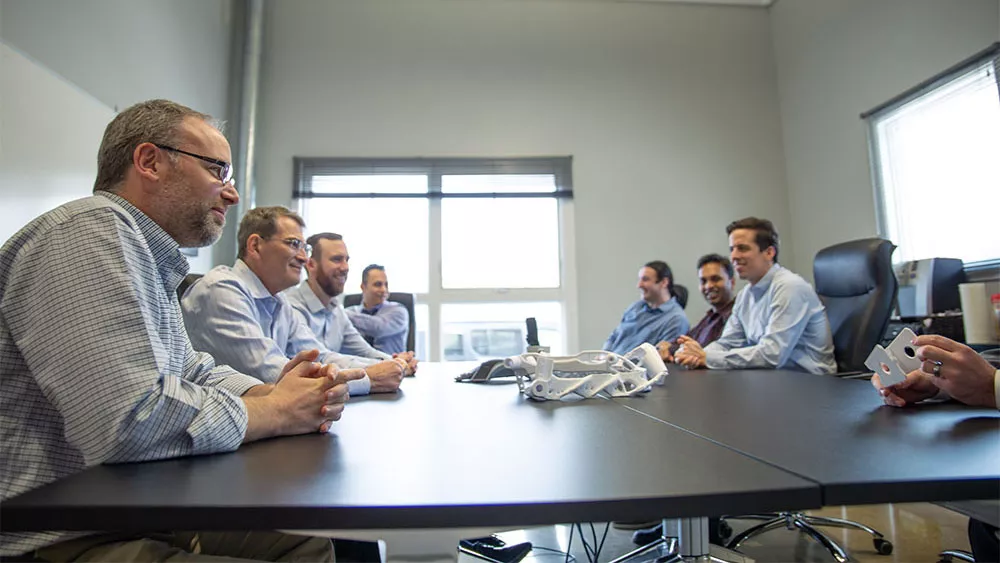
GoEngineer customers receive top-of-the-line tech support 12 hours a day (8am-8pm ET/5am-5pm PT), every weekday, from our 125+ certified technical specialists. Few partners can match GoEngineer's history supporting 3DEXPERIENCE since 2014.
They also receive complimentary yearly Application Mentoring Sessions, where they can explore their technology investment in a personalized and focused setting -- discuss needs, ask questions, or get demonstrations in any engineering area or product in the GoEngineer portfolio.
"I have never presented a problem to GoEngineer that they could not solve on the spot."
- Michael C.
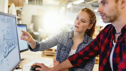
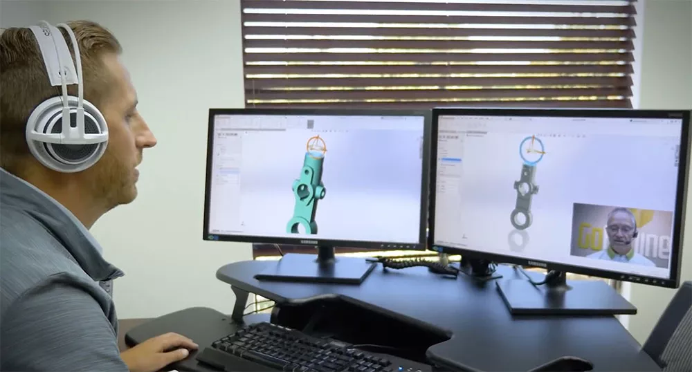
Training
GoEngineer customers get unprecedented access to software training in many forms, so they can choose what's right for them:
- In-person classes at nationwide GoEngineer locations
- Custom on-site courses by request
- Frequently-held, instructor-led online courses
- Self-paced online training with office hours for support
“Thank you, GoEngineer, for putting together an awesome training for SOLIDWORKS! I knew some CAD modeling software and how to use it, but this has really shown me how you can efficiently create 3D models and drawings. I highly recommend to anyone looking to better their skills in design."
- Adam T.
Extended Services
GoEngineer customers don't have to figure out all the difficult stuff in-house. They can enhance and customize their tech stack, ensure their systems stay healthy, and go above and beyond in-house capabilities by just hiring GoEngineer to take care of it:
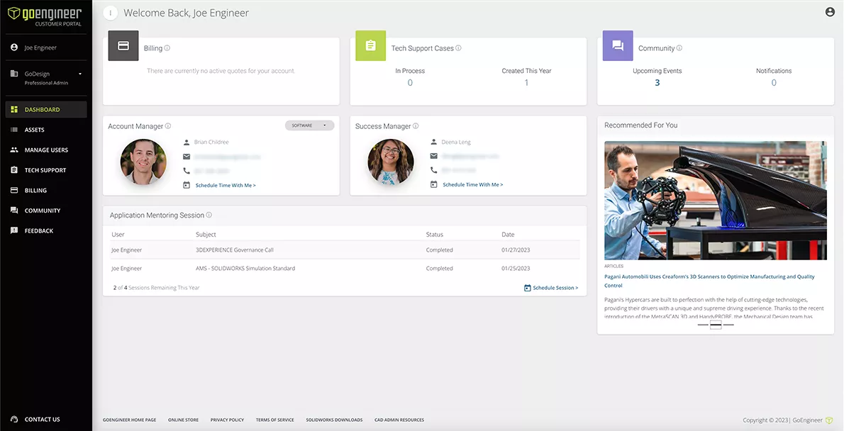
Customer Portal & COMMUNITY
GoEngineer customers get a comprehensive, realtime overview of their account in the Customer Portal:
- View assets, monitor status and expiration dates
- Manage users
- Create and manage tech support cases
- Schedule time with your account manager and success manager
- Schedule application mentoring sessions
- See billing history
- Submit feedback
- Active discussion forum of SOLIDWORKS & 3DEXPERIENCE users
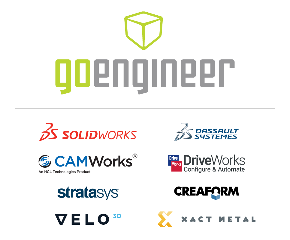
Unified Portfolio
GoEngineer customers simplify their business and improve their success with product development technology by unifying it all under one partner:
- Complete CAD-CAE-CAM-PLM ecosystems from SOLIDWORKS and Dassault Systèmes
- Complete 3DEXPERIENCE environments
- Partner products for automations, integrations, and extended functions
- Cadence Allegro X & OrCAD X PCB design software
- 3D printers from Stratasys and Formlabs
- 3D scanners from Creaform, Artec, and Peel
- Software IT, additive manufacturing, and product development services
Additional Resources
Take Advantage of GoEngineer’s Extensive Knowledge Base and Resources

Find a Solution
Our robust Knowledge Base contains over 12,000 resources to help answer your product design questions. From basic CAD questions to in-depth guides and tutorials, find your solution here. Find a Solution

PROFESSIONAL TRAINING
Improve your skills with professional training and certifications in SOLIDWORKS, CAM, 3D Printing, and 3D Scanning offered four ways: self-paced, online, on-site, or in-classroom. Certified Training Courses

BLOG
#1 Technical Resource Worldwide - Right at your fingertips. Search or browse through hundreds of SOLIDWORKS tips & tricks, additive manufacturing product developments, announcements, how-to guides, and tutorials. Blog
YouTube Channel
Our YouTube channel hosts hundreds of educational tutorials, product demonstrations, recorded webinars, and best practices for all of our products and services. GoEngineer's YouTube Channel
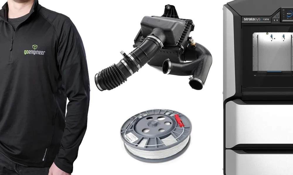
ONLINE STORE
Order 3D printing materials and consumables, enroll in SOLIDWORKS training classes, and buy official GoEngineer gear directly from our online store. Online Store
WEBINARS
Our engineering webinars are hosted by some of the top experts in the industry. They are always recorded, always free, and always offer a live Q&A. WEBINARS
3D Printing Services
Need to 3D print a part? Our Additive Manufacturing experts will 3D print your part and deliver it to you using the latest technology on one of our professional FDM, PolyJet and SL 3D printers. 3D Printing Services