CATIA V5 Parametric Optimization Guide
Integrated analysis and design is an approach that involves using software tools to analyze and optimize designs throughout the product development cycle. This approach can have several benefits for businesses, including improved product performance, reduced design cycle time, lowered manufacturing costs, and increased innovation.
CATIA V5 Product Engineering Optimizer promotes integrated analysis and design by allowing designers and engineers to improve their designs by using a variety of analysis tools and techniques throughout the product development cycle, reducing the need for costly changes down the road.
CATIA V5 Product Engineering Optimizer also supports multi-objective optimization, enabling users to optimize designs for multiple objectives simultaneously such as minimizing weight while maximizing strength or minimizing cost while maximizing performance.
This capability encourages users to consider the entire product lifecycle, including manufacturing, assembly, and maintenance. Furthermore, when an analysis is integrated with the design, it promotes collaboration between engineers from different disciplines.
Case Study
Creating a design for optimization in CATIA V5 Parametric Optimization involves defining the design parameters, setting up constraints and objectives, and generating a base model for optimization.
In this article, we’ll demonstrate this tool using a cantilever beam that was subjected to a point load. We use a profile shape for which the calculation of section properties is more complex. (Figure 1) The results obtained were validated using Abaqus/CAE software.
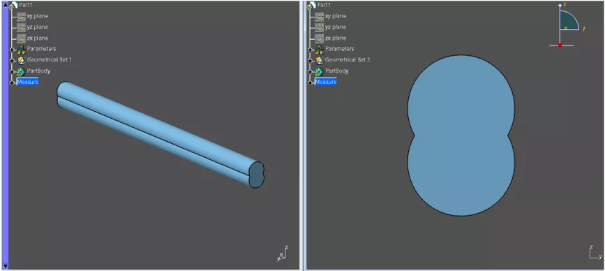
Figure 1: Beam profile
The steps below explain how we created the part used in the example.
Part Design
After opening the new part document, we created two new parameters (“Radius” and “Length”) with initial dimensions of 5mm and 3000mm, respectively. (Figure 2)
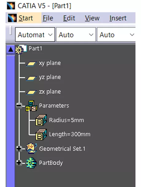
Figure 2: Initial parameters
Using the sketch, we drew a circular profile and linked the radius of the circle to the "Radius" parameter and the distance of the circle center to the symmetry line as “Radius”/2 parameter. (Figure 3)
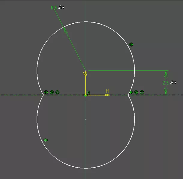
Figure 3: Profile sketch
The sketched profile was extruded and linked to the "Length" parameter (Figure 4), and we assigned steel material properties to the beam. (Figure 5)
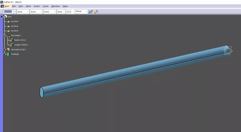
Figure 4: Extruded beam
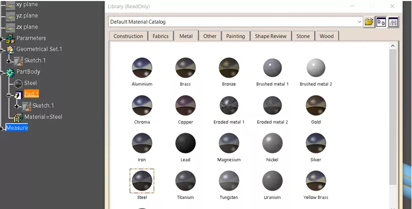
Figure 5: Steel as material selection
We used the Measure Inertia tool to measure the second moment of inertia of the beam profile. (Figures 6 & 7) In addition, we used Measure Inertia to obtain the mass of the beam, with the option to keep the measures.
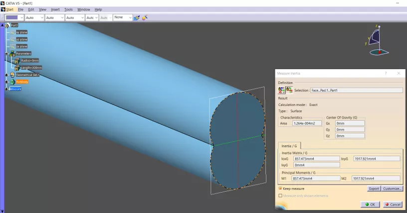
Figure 6: Second moment of inertia measure
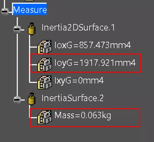
Figure 7: Second moment of inertia and mass measurements
Lastly, we used basic equations to create parametric relationships. (Figures 8 &9)
A complete list of parameters is shown in Figure 10.
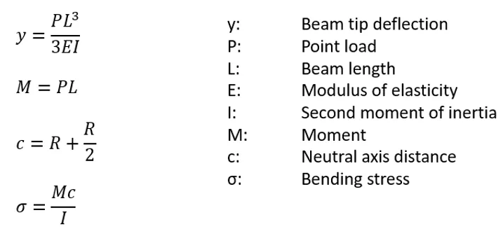
Figure 8: Equations
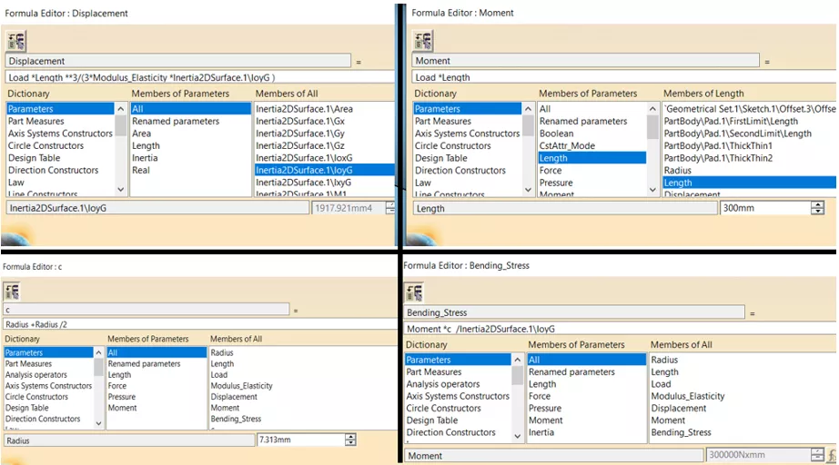
Figure 9: Additional parameters
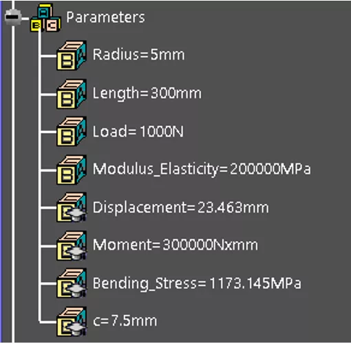
Figure 10: Parameter summary
To verify the proper setting of the equations, it should be tested how changing the constant parameters such as "Radius," "Length," and others affected the values of the parameters described through the equations.
Optimization
The goal of the optimization process was to find an optimal radius for the beam profile that would minimize the tip displacement under a 1,000N point load but prevent the mass of the beam from exceeding 0.10kg. In this example, stress was not used as a constraint but was calculated for informational purposes.
Beam length was kept constant throughout the process. The beam displacement was minimized as the section inertia of the beam increased, so it was expected that the optimization would find the optimal solution when the upper limit of the mass constraint was reached.
Steps for Conducting Parametric Optimization
Below are the steps for conducting parametric optimization to obtain the optimal design.
To optimize the beam profile, open the Product Engineering Optimizer workbench.
To start the optimization setup, click the Optimization button. (Figure 11)
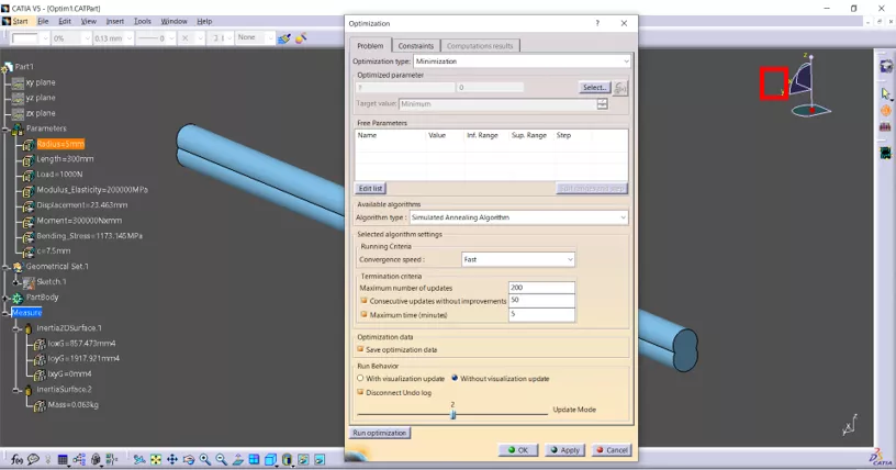
Figure 11: Optimization setup
Under the Problem tab, for the Optimization type, select Minimization. Under Optimized parameter, select Displacement - parameter created earlier. (Figure 12) This describes the optimization objective function.
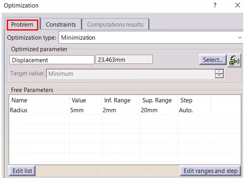
Figure 12: Objective function and variable setup
Next, under Free Parameter, select the “Radius” parameter with lower and upper bounds of 2mm and 20mm, respectively. This is the variable that will be optimized.
The mass constraint is set up under the Constraint tab. (Figure 13) When the mass constraint is set up, the “kg” unit should be added at the end of the equation. Additional constraints, such as bending stress, can be added as needed (but are not in this example).
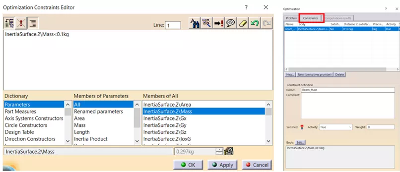
Figure 13: Constraint setup
To control the optimization process, several other setup parameters related to algorithms, running criteria, etc., will be left as is.
After Run Optimization is selected, name or select the MS Excel file in which the optimization results will be stored.
In this case, the optimization runs in less than a minute. Optimization progress can be observed in changing parameter and measurement values. Once the optimization is completed, the software lists all iterations. (Figure 14) These results can also be found in the saved MS Excel document.
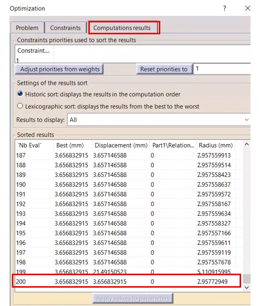
Figure 14: Optimization results
Graphical representation of the optimization progress can also be plotted. (Figure 15)
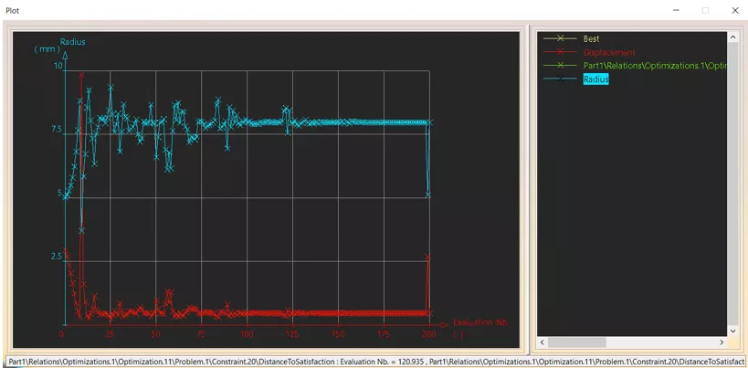
Figure 15: Optimization progress
At the end, the parameters are updated with the iteration that resulted in the best outcome. (Figure 16)
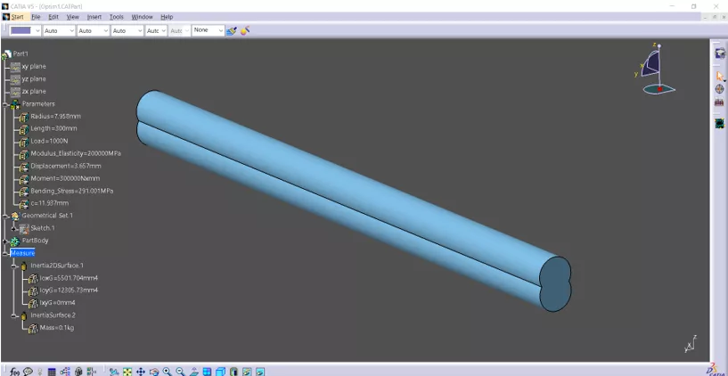
Figure 16: Optimized beam
The results show that the calculated radius of 7.958mm resulted in a tip displacement of roughly 3.657mm while the upper limit of the beam mass of 0.1kg was reached. A max bending stress of roughly 291MPa was also calculated.
Validation
Validating the accuracy of the results is up to you and requires FEA software. In this example, we used Abaqus/CAE. We configured the FEA model as a cantilever beam with one end fixed and a point load of 1,000N applied on the other end. (Figure 17)
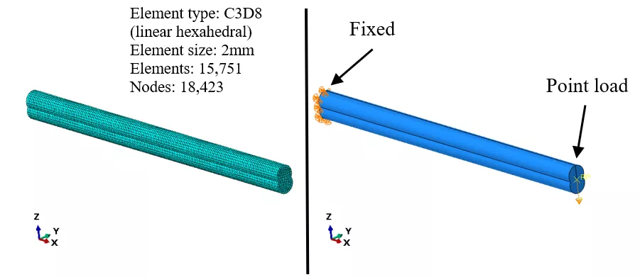
Figure 17: FEA model setup
Additionally, Figure 17 provides information about the element type and size used for the analysis. For the analysis, Von Mises stress was chosen as the failure criterion. The FEA outcomes were found to be in good agreement with those obtained from the CATIA Optimizer, shown in Figure 18 and summarized in Figure 19.
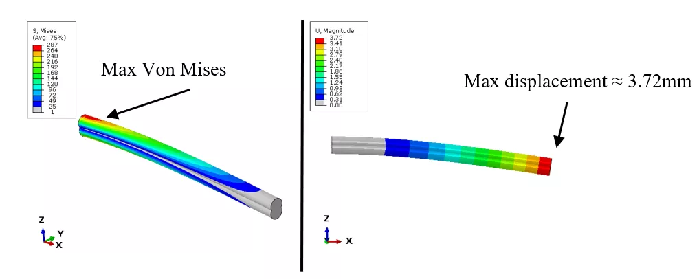
Figure 18: FEA results
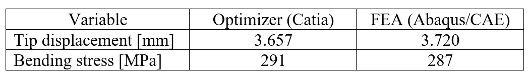
Figure 19: Results summary
Conclusion
As you can see, a substantial amount of engineering work was performed during the design phase. While our cantilever beam example may have been simple, the principles discussed are transferable and can be applied to more complex designs.
Want to Learn More?
![]() Easing the SOLIDWORKS-to-CATIA V5 Transition - Webinar
Easing the SOLIDWORKS-to-CATIA V5 Transition - Webinar
Abaqus and CATIA Now Available from GoEngineer: NOT Just for Enterprise!
CATIA V5 vs 3DEXPERIENCE CATIA: Interface, Licensing, Installation, & Setup

About Dragan Maric
Dragan Maric is a Sr. Simulation Specialist at GoEngineer. He earned a BSE & MSE in Mechanical Engineering from the University of Michigan. Although Dragan has over 18 years of FEA experience, his main focus is on product development.
Get our wide array of technical resources delivered right to your inbox.
Unsubscribe at any time.