How to Create a Lip/Groove Feature in SOLIDWORKS
This guide will show you how to create a Lip/Groove feature in SOLIDWORKS for plastic parts. It can be created in a multi-body part or in an assembly by editing one of its components. For this example, we will create the lip/groove feature in an assembly file.
To access the Lip/Groove feature go to Insert > Fastening Feature > Lip/Groove.
Note: If this feature is unavailable, it means that you are not in Edit Part mode.
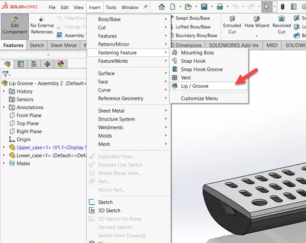
Figure 1: Location of Lip/Groove feature
Body/Part Selection
When starting the Lip/Groove feature, its PropertyManager will ask you to select the component on which to create the groove.
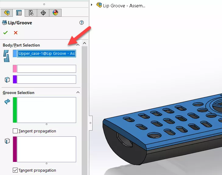
Figure 2: Select the component for the groove
Upon component selection, you’ll see the PropertyManager expand with more options. The next selection down the line is for the component on which to create the lip.
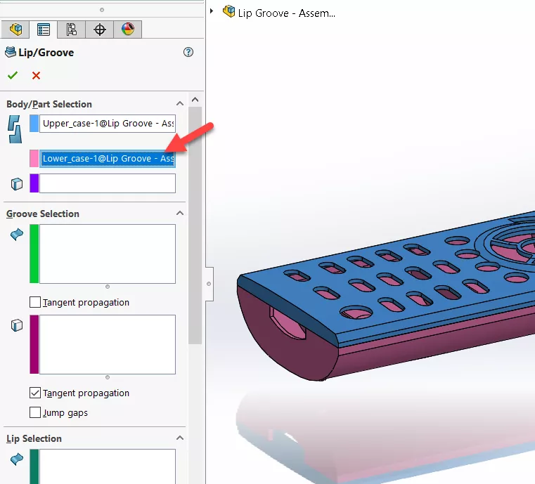
Figure 3: Select the component for the lip
With both lip and groove components selected, you are prompted to select a plane, face, or edge to define the direction. This is optional if all the selected faces on which to create the lip and groove are planar have the same normal. For this example, I’ll select a plane exactly between the components.
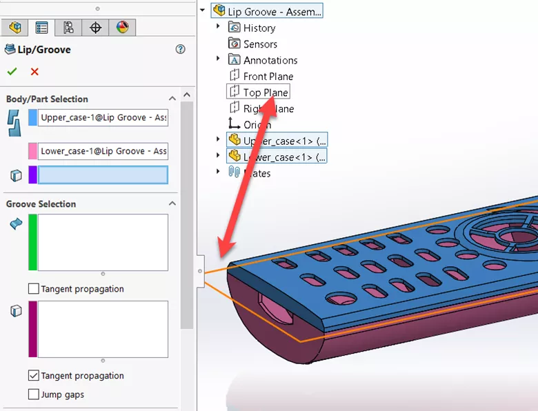
Figure 4: Select a planar or face for the direction
Groove Selection
In the Groove Selection section, you are asked to select the face where the groove will be cut into and the edge on which to cut the material out of relative to the selected face. You also have the option to tick Tangent propagation, which extends the selection to tangential faces.
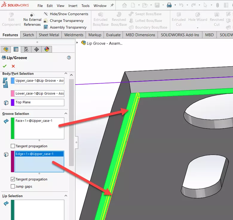
Figure 5: Face and edge selection for the groove
Lip Selection
The face and edge selection for the lip follows the same logic as the groove, see Figure 6, except if you have intersecting edges. Thankfully, there is the Jump Gaps option we can turn on to fill in those gaps. See Figure 7.
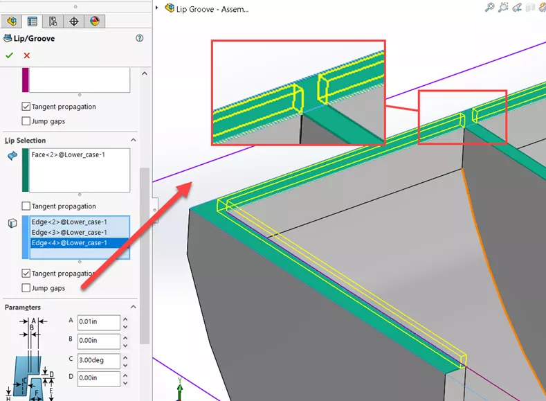
Figure 6: Face and edge selection for the Lip without Jump Gaps
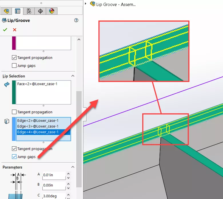
Figure 7: Jump Gaps option turned on
Parameters
In this section, specify the lip/groove parameters and how they interface. SOLIDWORKS’ illustration does a good job explaining what each dimension is, but if you need further explanation, see Figure 8 for a more detailed explanation of each dimension.
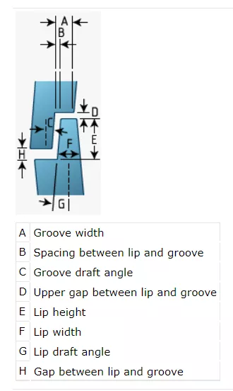
Figure 8: Lip/groove parameter description
To link dimensions, turn on the Link Matched Values option. This is a fool-proof way to ensure that if you change the groove width, the lip width will match.
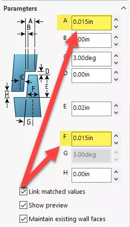
Figure 9: Link Matched Values
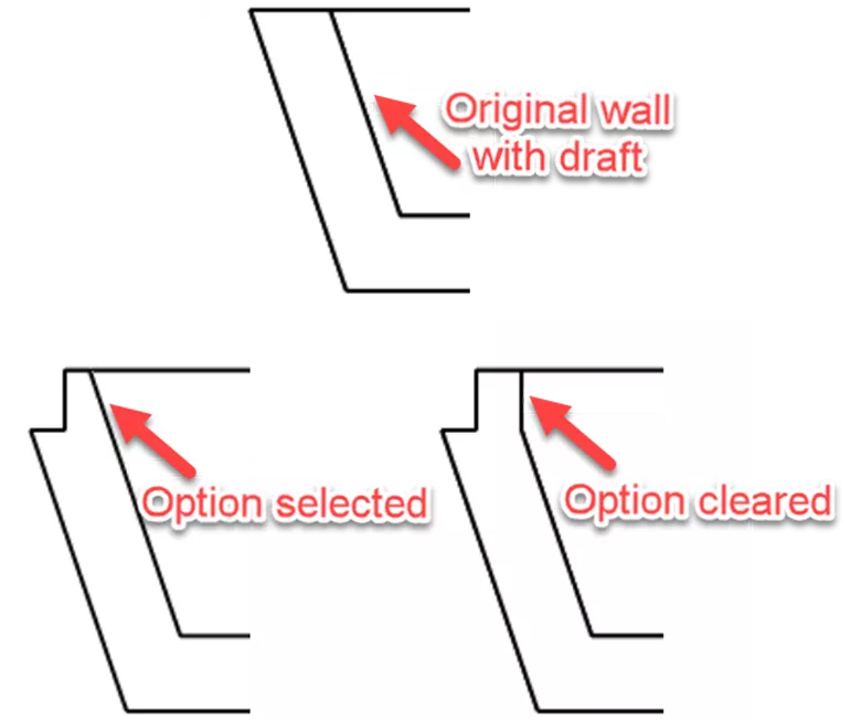
The option to Maintain Existing Wall Faces applies only to models that have drafts on their walls. Select this option if you desire and it is possible to extend the wall draft to the top of the lip. By clearing this option, faces will be added to the draft.
I hope you found this tutorial helpful. Check out more SOLIDWORKS tips and tricks below.
More SOLIDWORKS Tutorials
SOLIDWORKS Combine Feature Tutorial
Working with Exploded Views in SOLIDWORKS
SOLIDWORKS Path Mate Explained
How to Mirror Parts in SOLIDWORKS Two Different Ways

About Rodolfo Gutierrez
Rodolfo Gutierrez is a Mechanical Engineer by profession specializing in SOLIDWORKS, Routing, PDM, Sheet Metal, and Weldments. Lucky husband and goofy dad. Loves productivity hacks.
Get our wide array of technical resources delivered right to your inbox.
Unsubscribe at any time.