Displaying Expanded Metal in SOLIDWORKS Without Designing It
What is Expanded Metal?
Expanded metal is a type of sheet metal that has been cut and stretched to form a regular pattern to look like a mesh. It is commonly used for fences, walkways, grates, and as metallic lath to support plaster or stucco.

While the part itself is nothing more than a plate with holes in it and is not much to sketch and pattern - this geometry in CAD is a monster!
Think about how many faces, how many edges, and how many points the video card alone must generate! I’ve seen a 30in x 29.5in plate that had 3,500+ holes and weigh over 10MB. It had more than a three minute rebuild time, almost 90,000 triangles, and my graphics performance was gone (until after the rebuild).
Customer Requirements
Customers often need to show details, need a model for a presentation, or on a drawing for the shop floor - it just has to be there! So how do we get the best of both worlds? How do I make a model that is solid in the 3D Model/Assembly that I can see through but see it in the Drawing and it doesn’t block my other models?
Well, with some trickery and magic, this can happen...trickery and magic being Display State, patience, and a good video card!
3D Modeling
Building Expanded Metal as a 3D model is not difficult but it will bog down your computer system and SOLIDWORKS. The calculation will take a very long time to process because of the high count of Edges/Faces.
An option to display a part as “Expanded Metal”, would be to use a texture. This technique can only be used if your computing system is using a video card that is “RealView Graphics” compliant. You can tell if your system supports this by going to the Monitor drop-down in the SOLIDWORKS graphics window. If the icon displays a grey sphere then you do not have this capability.
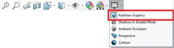
Note: This option is video card specific.
Once you verify that the option is turned on, open a new part file, and select the desired plane in the FeatureManager tree for the correct orientation of the expanded metal plate. After creating a new sketch, draw a rectangle to size and dimension it as needed. This sketch is here to create a surface using the “Planer Surface” command. We are using a surface, so the texture is not double-sided.
Display States and adding a Texture
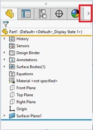
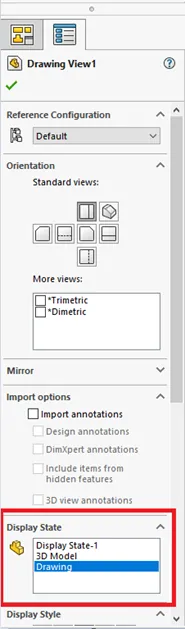
Once the surface is created, you will need to create two “Display States”, one for the model and the other will be for the drawing. In the FeatureManager, select the Display State chevron to expand the manager; this will give you access to the required options.
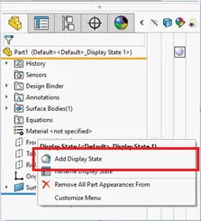
Right mouse within the Display State Pane and select the option to “Add Display State”, when prompted, give this state the name “3D Model”.
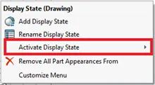
Repeat this step to create a Display State for the drawing, calling it “Drawing”. We will need to activate the “3D Model” Display State. Right mouse back inside of the display state pane to see the selection window. Hover your mouse pointer cursor over the “Activate Display State” option and select the “3D Model” choice.
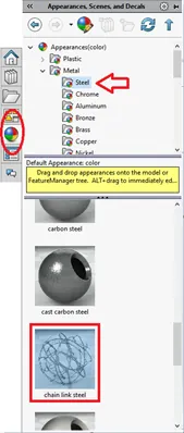
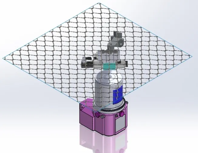
Now you will add in texture to make the part look as if it is Expanded Metal. We will be using the “Chain Link Steel” map to do this. In the SOLIDWORKS Task Pane on the right-hand side of the screen, select the four colored ball icon for “Appearances”. Expand the “Appearance” folder then expand “Metal” and then “Steel”. Here you will find the “Chain Link Steel” texture.
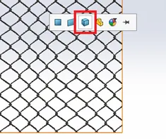
Using the left mouse button, drag the texture icon over to the face of the surface and let go. Make sure you do not move your mouse much after you release, doing so will cause the pop-up to disappear. In the pop-up window, select the “Bodies” option to assign this texture to the surface body.
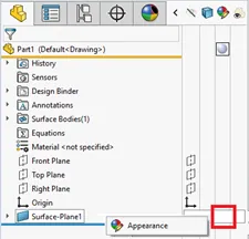
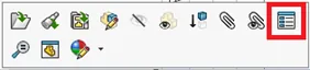
Head back to the “Display State” Pane and activate the “Drawing” display using the same method we used to activate the “3D Model” display. After you have done this, the chain appearance will go away taking us back to the original color of the surface. In the FeatureManager tree, go to the line item for the “Surface-Plane 1” feature and click the third option in the display pane as indicated in the graphic below and choose the “Appearance” option.
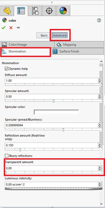
The “Color” property manager will open so we can play with the options for the surface transparency. Activate the “Advanced” controls and select the “Illumination” tab. Slide the “Transparent amount” to the right, for a value of 1, making the surface completely transparent. Complete this task by hitting the green check to apply.
Setting the Mass
Normally when we create a SOLIDWORKS part file, we set the Material, build the part, and the mass weight is automatically created for us. But this cannot be done with this part file with it being not more than a surface, there is no volume to it. So, we need to add a solid feature to trick the system to think there is.
Select the same plane that we used to build the surface sketch on and create a new sketch. At the part's origin, draw in a rectangle and give it dimensional values; the size of the model should be fine. Extrude the Sketch to the desired thickness of the model. Rename this feature to something like “Boss-For Mass”. In the FeatureManager of the part, right mouse on the tree item called “Solid Bodies (1)” and hide all bodies.
Note: It is important to hide this to all display states.
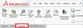
Once the solid is created, we can override the mass properties. With the part opened inside of SOLIDWORKS, in the CommandManager activate the “Evaluate” tab, and here you will see the “Mass Properties” command, select the icon to launch the tool.
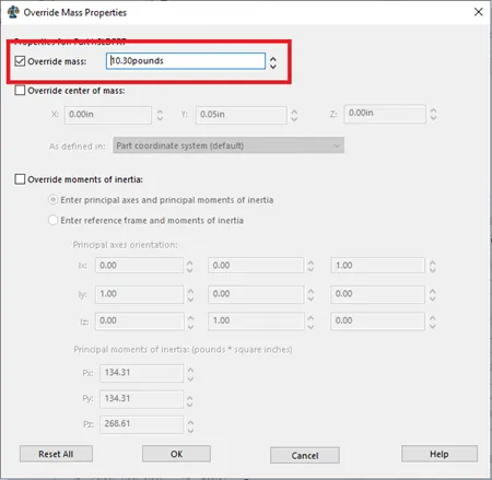
After the dialog opens, select the option in the top left corner called “Override Mass Properties”. After doing so a new window appears. Here, select the option “Override mass” and the text dialog will become active so you can type in the desired value. Unfortunately, SOLIDWORKS will not calculate these numbers for you so you will have to research the value. The best place to do this would be the vendor's website.
Close all the windows and save the part file.
Assembly Modeling
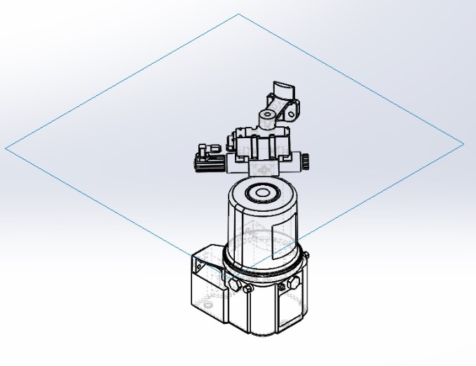
In the part file that we created, activate the display state, “3D Model” and create the assembly file as normal. Add the necessary Parts/Assemblies and position them as needed using the mate tool. When mating to the “Expanded Metal”, you can use surface faces and planes to add in constraints.
Assembly Display States and Display Styles
Again, we will be building two new display states as we did in the part file. Open the “Display State” Pane in the assembly. Right mouse within the pane and create two assembly display states calling them “3D Model” and repeat for “Drawing”. The purpose of the drawing display state is to again, trick the system to display the data in the 2D drawing file.
Once you have the two new display states, make sure that the “Drawing” display is active. We will be setting parts in this display state to have different visual styles. Left mouse on the “Expanded Metal” part in the FeatureManager tree in the assembly file. Here, you should receive a context-sensitive pop-up window that is relative to that part's options. Select the icon in the top right corner called “Component Properties”.
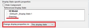
After selecting “Component Properties”, a dialog will appear on the screen. This dialog gives you the ability to change the options of the part or assembly that you selected. In the middle of the active dialog window, you will see a “Display State specific properties” section and set the “Referenced Display State” option to “Drawing”. Verify the option “This display state” is selected for the drop-down choice in “Change display properties in:”.
Close this window.
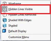
Next, while still in the “Drawing” display state of the Assembly, we will need to switch all of the parts to “Hidden Lines Visible”.
Note: Keep the default display to "shaded with edges"
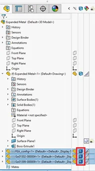
In the FeatureManager tree, select all the parts/assemblies except for the “Expanded Metal” part, and make sure that you use your “CTRL” or “Shift” key when selecting these files. Then, in the “Display State” pane, the second column is used to change the “Display Style” of individual or groups of parts/assemblies, by default it is set to “Default Display”. With the “CTRL” key still held down select one of the blue square icons to change this option. Set this option to your desired display for the drawing file, typically “Hidden Lines Visible”.
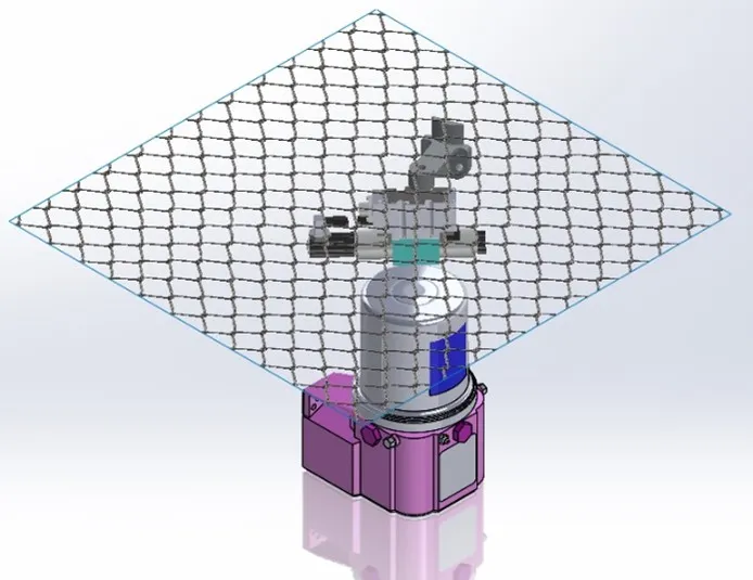
Toggle between the two display states to see the visual difference.
"Drawing" "3D Model"
Note: Leave the assembly in the "drawing" display state.
Creating the Drawing
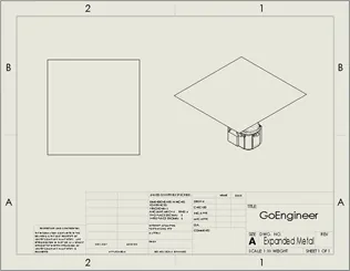
Create your drawing file as normal. Select your Drawing Template, choose your sheet size, and place your views. You will not be able to see any of the part details that are being obstructed by the “Expanded Metal” part.
Select one view to make sure you are still in the “Drawing” Display State.
Using the “CTRL” key and select all of the views that you need to see through the “Expanded Metal” part. Switch these views to “Shaded with Edges” mode, using the “Display Style” drop-down in the graphics window. You will now be able to see the parts as “Hidden Lines Visible”.
![]()
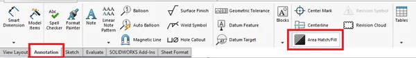
Once you can see these parts, we will add the “Lattice” pattern to have a visual display of the “Expanded Metal”. This can be achieved with the use of the “Area Hatch/Fill” command located in the “Annotation” tab of the CommandManager.
In the dialog window of the “Area Hatch/Fill” command, select “DIN 128 Plastic” from the drop-down. Set the scale to 0.25 and the angle to 50.00deg. Select the face of the surface to apply the pattern. Repeat this step to display the lattice in the views that it is necessary to see the pattern.
Note: These values are optional based on your liking.
Hide the “Expanded Metal” Part.
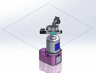
Once the pattern is in all the views, we may need to “Hide” the part. An easy way to do this is to switch the views display to “Shaded” as we did before when switching to “Shaded with Edges”. By switching to this display style, the outer edges of the surface will disappear, the part is still there for the B.O.M. and will be selectable for ballooning.
![]()
Adding balloons
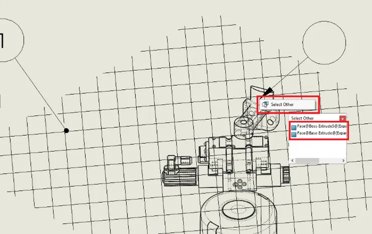
On the drawing, zoom into a view of balloons. When you select the balloon command, hover over the lattice pattern and the balloon tool will immediately find the “Expanded Metal” part. With that part technically there, the parts behind the lattice will not be able to be easily selected, unless you use the right mouse option. Hover over the face or edge of the part you wish to balloon. Right mouse over the assembly part that needs ballooning, in the pop-up menu, select the option “Select Other”. A new window will appear with options, if you hover over the items in the list, it will highlight faces in the view, select the appropriate face or edge and then place the balloon.
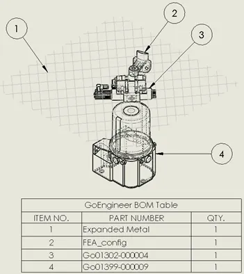
Finish the drawing file by completing the balloon process, add any necessary notes or dimensions, and add in your bill of material.
Note: If any models revert to a "shaded" display, you can correct this by holding CTRL + Q.
Learn More About SOLIDWORKS
Top 10 SOLIDWORKS Webinars in 2020
SOLIDWORKS 2021: Redo is Improved!

About James Ortiz
James Ortiz joined the VAR community in 1997 with DASI Solutions (now GoEngineer) as the SOLIDWORKS Technical Support Manager for Michigan, Ohio, Indiana, and northern Kentucky. James then joined the pre/post-sales team to perform product demos, SOLIDWORKS and PDM implementations, and produce a multitude of content for events and trade shows. James is currently a SOLIDWORKS Training Specialist based out of Auburn Hills, MI.
Get our wide array of technical resources delivered right to your inbox.
Unsubscribe at any time.