Edit Flattened Harness Routes: SOLIDWORKS Electrical 3D
This tutorial explains how to edit flattened harness routes in SOLIDWORKS Electrical 3D. Flattened representations of a SOLIDWORKS harness can be difficult to read in its default state. With the 'Edit Flattened Route' command, a high-quality representation of the flattened route can be created with ease.
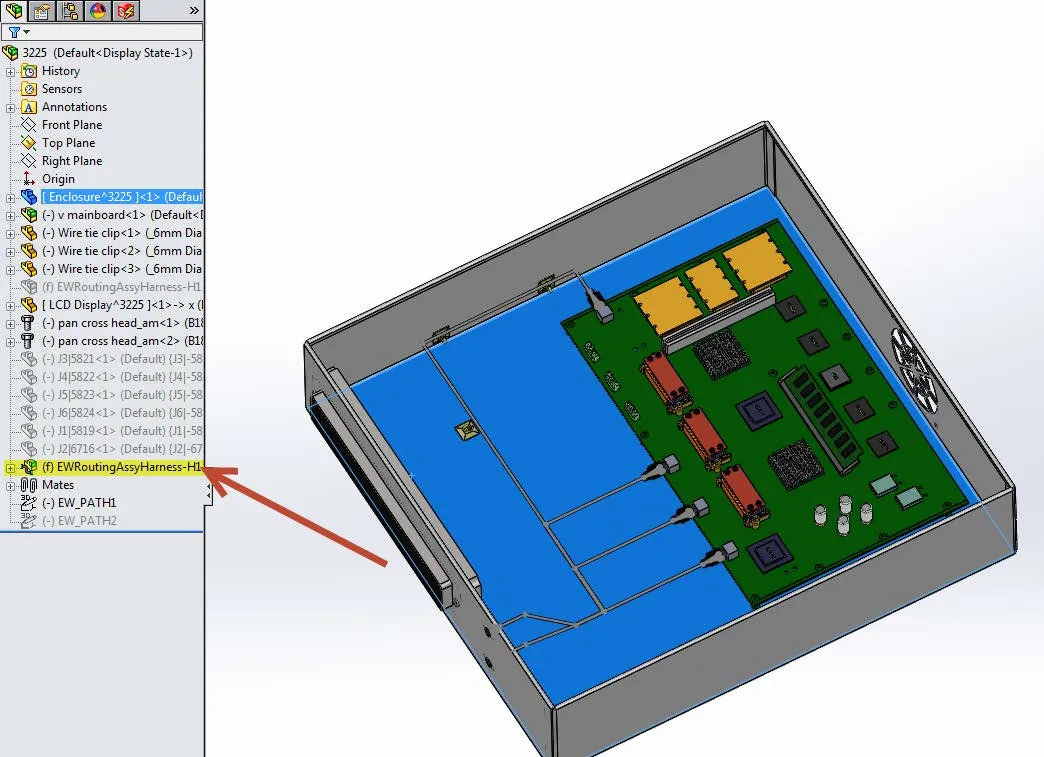
Once the harness is routed in 3D, there is a new routing sub-assembly in the FeatureManager Design Tree.
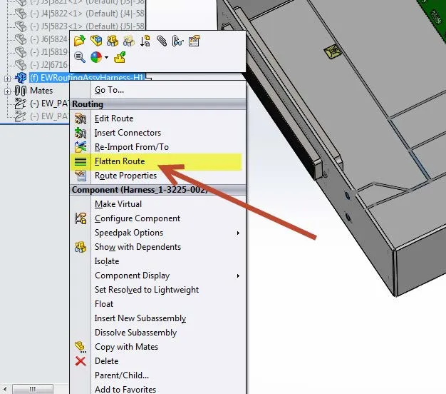
Right-click the routing sub-assembly and select 'Flatten Route.'
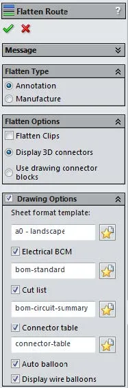
Select the type of flatten route (defined below) and select the different drawing options that are required in the Flattened Drawing. Select OK (green check mark).
- Annotation allows the creation of a flattened configuration that is displayed using the standard drawing sheet with views.
- Manufacture allows the creation of a flattened configuration that is displayed true size on a formboard.
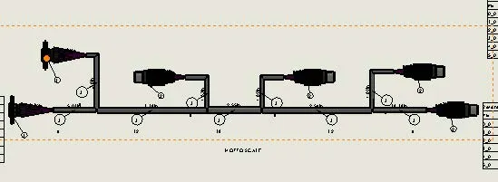
A flattened harness assembly and a flattened harness drawing are created and opened. The flattened harness drawing will be the file that is displayed. If the harness assembly is too complex the flattened representation can be cluttered.
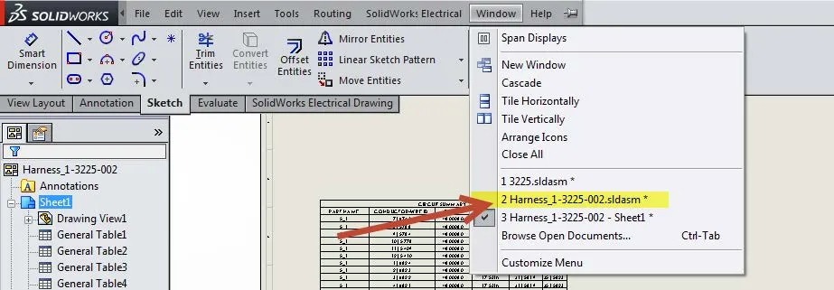
Open up the flattened harness assembly. Go to Window and select the file. Alternatively, use CTRL+Tab to get to the right document.
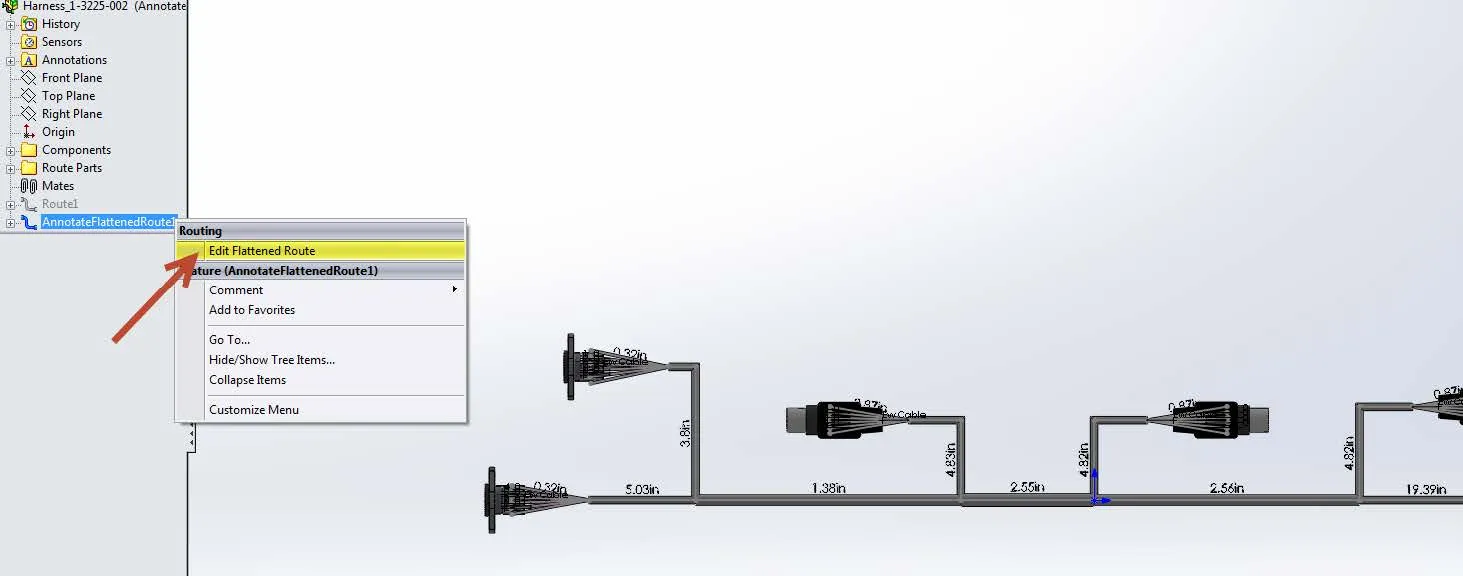
Right-click the AnnotateFlattenedRoute# and select 'Edit Flattened Route.'
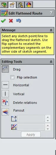
Five tools aid in editing the flattened route
- Drag - Enables the user to drag any sketch point or line in the flattened sketch to the desired position. The 'Flip Selection' check box can be used to select the complementary segments.
- Horizontal – Constrains the selected segment horizontally.
- Vertical – Constrains the selected segment vertically.
- Delete Relations – Delete relationships that segments can be dragged to any position.
- Fanout – Enables the manipulation of the fanout segments. The 'Position Angle' defines the position of the fanout with respect to the base segment. The 'Spacing Angle' defines the spacing between fanout segments.
Once the manipulation is completed, hit OK (green check mark). Navigate back to the flattened harness drawing and the changes to the flattened harness assembly will automatically propagate to the drawing.
More SOLIDWORKS Electrical Tutorials
An Easy Way to Add Watermarks in SOLIDWORKS Electrical
Why Won't My Wires Route in SOLIDWORKS Electrical (Part 1 and Part 2)
SOLIDWORKS Electrical 2020 Leader Lines - What's New
Wrapping Attribute Text in SOLIDWORKS Electrical
SOLIDWORKS Electrical Videos
![]() Taking the Next Step with your Schematics
Taking the Next Step with your Schematics
![]()
About GoEngineer
GoEngineer delivers software, technology, and expertise that enable companies to unlock design innovation and deliver better products faster. With more than 40 years of experience and tens of thousands of customers in high tech, medical, machine design, energy and other industries, GoEngineer provides best-in-class design solutions from SOLIDWORKS CAD, Stratasys 3D printing, Creaform & Artec 3D scanning, CAMWorks, PLM, and more
Get our wide array of technical resources delivered right to your inbox.
Unsubscribe at any time.