Inserting a Partial Connector in SOLIDWORKS Electrical
This article shows you how to define a connector that only displays specific pins in SOLIDWORKS Electrical.
After creating and inserting a multi-pin connector (in this example, four pins of a 10 pin connector are displayed), edit the component properties.
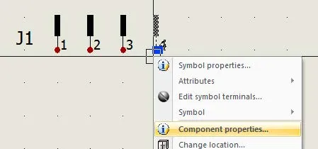
Select the Manufacturer part and circuits tab.
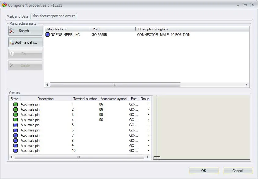
The green boxes indicate pins that are associated with a symbol in the scheme, the blue boxes show available pins that do not have a symbol associated with them. You can drag the pins around in this dialog, in this case, I have dragged the green boxes to the position of the pins I want to represent in the schematic.
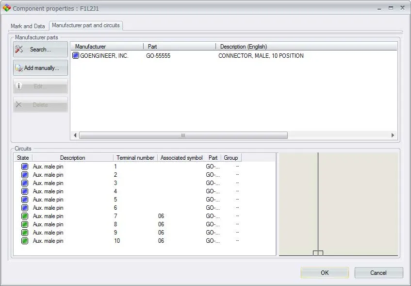
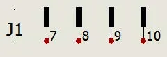
The result is that the scheme now represents pins seven through ten.
I hope you found this guide helpful. For more SOLIDWORKS Electrical tips and tricks check out the links below.
More SOLIDWORKS Electrical Tutorials
Easy Way to Add Watermarks in SOLIDWORKS Electrical
Why Won't My Wires Route in SOLIDWORKS Electrical? Part 1 & Part 2
![]()
About GoEngineer
GoEngineer delivers software, technology, and expertise that enable companies to unlock design innovation and deliver better products faster. With more than 40 years of experience and tens of thousands of customers in high tech, medical, machine design, energy and other industries, GoEngineer provides best-in-class design solutions from SOLIDWORKS CAD, Stratasys 3D printing, Creaform & Artec 3D scanning, CAMWorks, PLM, and more
Get our wide array of technical resources delivered right to your inbox.
Unsubscribe at any time.