Managing External References in SOLIDWORKS Assemblies
In our SOLIDWORKS Top-Down Assembly Modeling Quick Tip, we discuss the difference between Bottom-Up and Top-Down Assemblies and demonstrate how to use Top-Down Assembly techniques to create a part with external references to another in the assembly.
With these external references in place, the new virtual part will update when changes to the parent file are made. A best practice is to use Top-Down Assembly methods for preliminary design work. Once the design is finalized, it is recommended to replace the external references with sketch relations and dimensions to drive the features within the part file.
In this article, we will demonstrate how to replace those external references.
Removing/Replacing External References
As you can see in Figure 1, the file was created using references external to the file. The symbol (->) next to the part name Part2^Top Down Assembly means that there are external references to the part. The face of the weldment tube was used as the reference plane, the sketch was created using offset entities, and the finished part is fully constrained with an InPlace mate. This is like the part being Fixed in position.
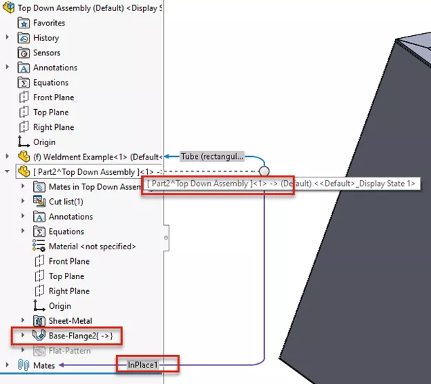
Figure 1: Virtual Part with External references
Right-click on the part file in the Assembly FeatureManager design tree and select Open Part. (Figure 2). For this tutorial, we will save the file as an External file so that it is no longer a virtual part.
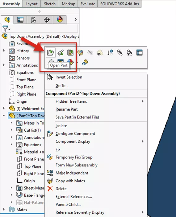
Figure 2: Open the Virtual Part in a new window
With the file open, go to File > Save As, and give it a new name. Don’t worry, the Parent Assembly will update with the new file name. Click OK.
Right-click on the Feature Base-Flange 1. Click on External References to review what entities are being referenced outside of the Part file.
Note: You might be tempted to select Break References instead of replacing the references. We do not recommend this, as the software will blindly break the references and cannot be reversed.
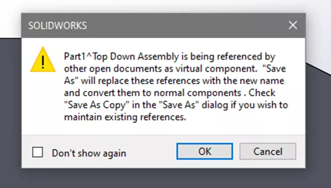
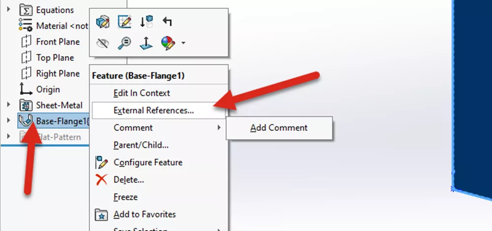
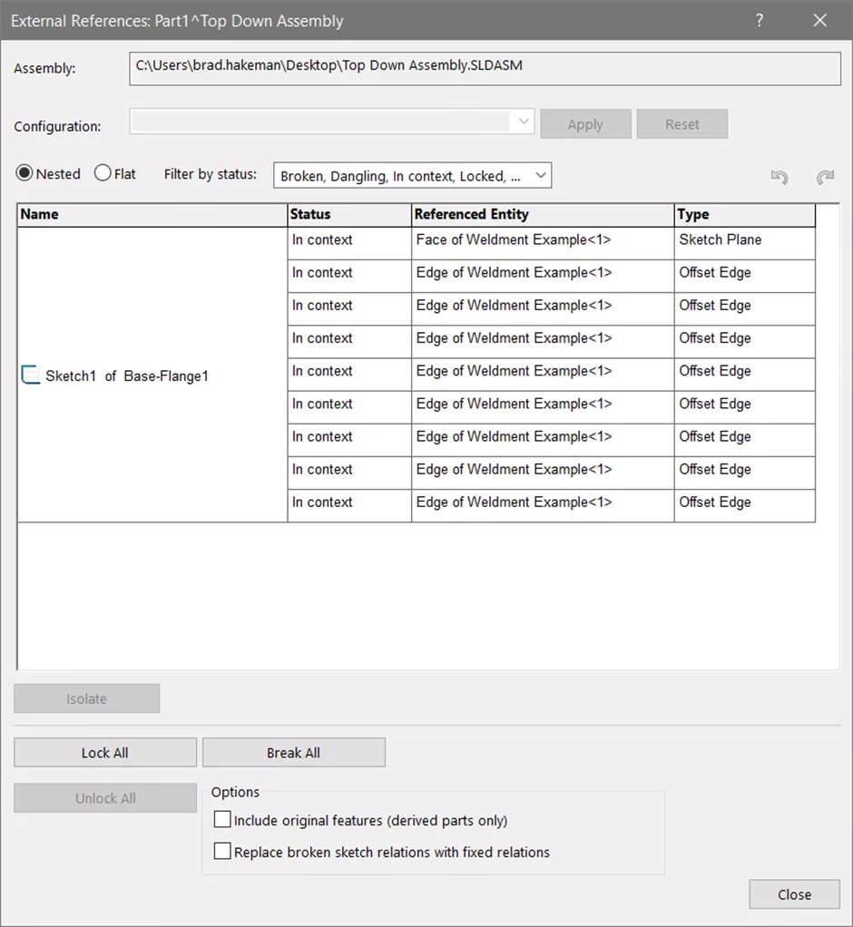
Figure 3: Select “Show External References” to view a list of External References used to create Sketch1 of Base-Flange1 Feature. Resist the urge to select “Break All”
Right-click on the sketch and select Edit Sketch Plane. (Figure 4) Replace the plane with the Front Plane of the Part file replacing the original selection of the outer face of the weldment tube.
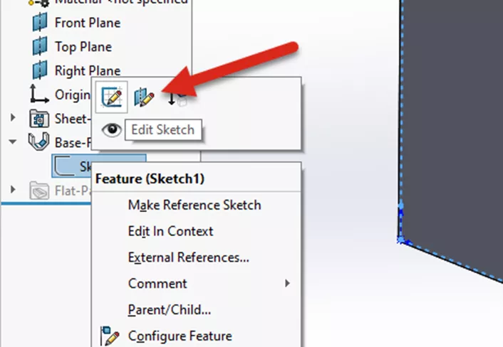
Figure 4: Right-click on the sketch and select “Edit Sketch Plane”
The next steps will be to replace the sketch relations that are external to the part file and fully define the sketch for the feature.
Right-click on the Sketch of the Base-Flange feature and select Edit Sketch. Click on Display/Delete Relations to view a list of Sketch Relations. (Figure 5) Delete these relations with the Delete All command.
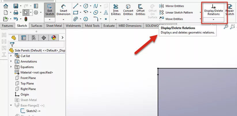
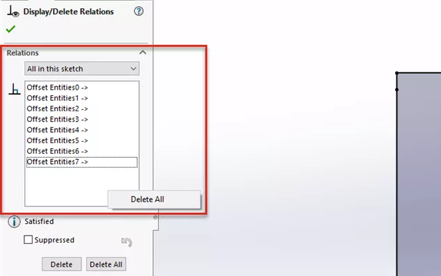
Figure 5: Edit the sketch and remove the Sketch Relations that are external to the part file
Now that the sketch is under-defined, we need to add Dimensions and possibly Sketch Relations.
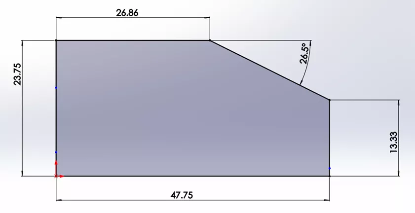
Figure 6: Add dimensions to fully define the sketch for the Feature
As you can see in Figure 7, the updated part file is free of External Relations with the parent assembly.
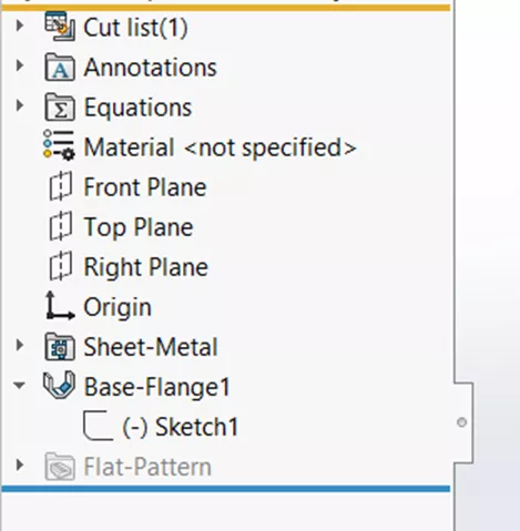
Figure 7: Updated part file with no external references
Finishing Touches
The final step is to replace the InPlace mate in the assembly with fully defining mates to better locate the part. (Figure 8). Width Mates are used in this example to keep the panel centered on the side of the weldment.
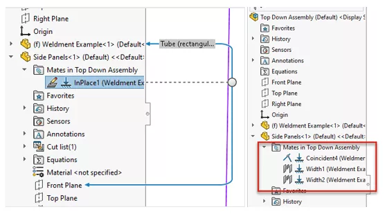
Figure 8: Before and after
I hope you found this SOLIDWORKS tutorial helpful. Check out more SOLIDWORKS tips and tricks below.
More SOLIDWORKS Tutorials
SOLIDWORKS Drawing Performance: Turn Off Detailing Mode
SOLIDWORKS Routing Electrical Route Through Clips
SOLIDWORKS FilletXpert Tool Tutorial
Restore SOLIDWORKS Thumbnails in Windows
Applying a New SOLIDWORKS Drawing Sheet Format to Existing & Future Drawings
![]()
About GoEngineer
GoEngineer delivers software, technology, and expertise that enable companies to unlock design innovation and deliver better products faster. With more than 40 years of experience and tens of thousands of customers in high tech, medical, machine design, energy and other industries, GoEngineer provides best-in-class design solutions from SOLIDWORKS CAD, Stratasys 3D printing, Creaform & Artec 3D scanning, CAMWorks, PLM, and more
Get our wide array of technical resources delivered right to your inbox.
Unsubscribe at any time.