SOLIDWORKS Top-Down Assembly Modeling Quick Tip
There are two methods for creating a SOLIDWORKS Assembly file: Bottom-Up assembly modeling and Top-Down assembly modeling. In this quick tip, we’ll explain the difference between the two and demonstrate how to create a Top-Down assembly.
Bottom-Up Assembly vs Top-Down Assembly
What is the difference between Top-Down assembly and Bottom-Up assembly modeling in SOLIDWORKS?
Bottom-Up Assembly
A Bottom-Up assembly starts with completely modeled SOLIDWORKS Part files before adding them to a SOLIDWORKS assembly. All solid bodies and features (Cuts/Bosses/Fillets) have been added prior to assembling the files. Component Part files added to the assembly are positioned using Mate features. The Mates relate faces and edges of the component parts to planes and other faces/edges in the assembly. Think of this method as if you were building the assembly in the real world.
Top-Down Assembly
In a Top-Down assembly, you’re working in the opposite direction. One or more features of a part are defined by something within the assembly, such as a layout sketch or the geometry of another part.
As you will see in the following steps, we will start with a SOLIDWORKS assembly with a single Weldment Part file already in place. Using Top-Down assembly techniques a Sheet Metal part will be modeled directly within the Assembly file.
Creating a New Assembly
In this example, we have a new SOLIDWORKS Assembly file with a Weldment Part file to start from. The design intent is to add Sheet Metal panels to the sides of the Weldment. (Figure 1)
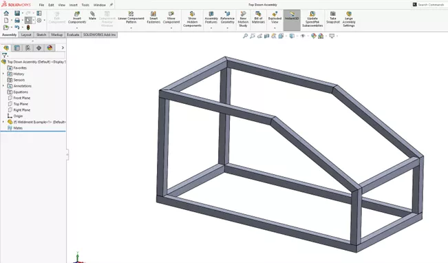
Figure 1: New assembly with a Weldment Component
In the Assembly tab of the CommandManager toolbar, select Insert Component > New Part. (Figure 2)
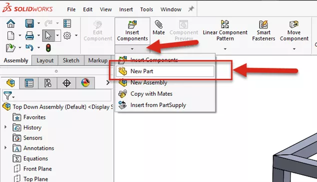
Figure 2: Insert Component > New Part
Select the outer face of the side tubes of the Weldment.
Note that the new part has been added to the Assembly FeatureManager Design Tree. (Figure 3)
Also note that the file is shown in blue because it is in Edit Component mode, and a new Sketch1 has been activated automatically.
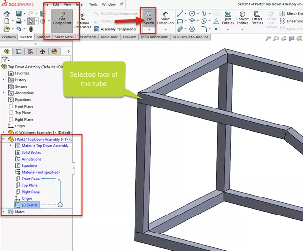
Figure 3: New Part shown in edit mode with an active Sketch command
Since we want the Sheet Metal part to match the shape of the Weldment structure, select the Offset Entities Sketch feature and the outside edges of the tubes. (Figure 4) An offset distance of 1/8” (0.125) has been set for design intent and Assembly clearances.
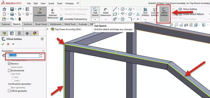
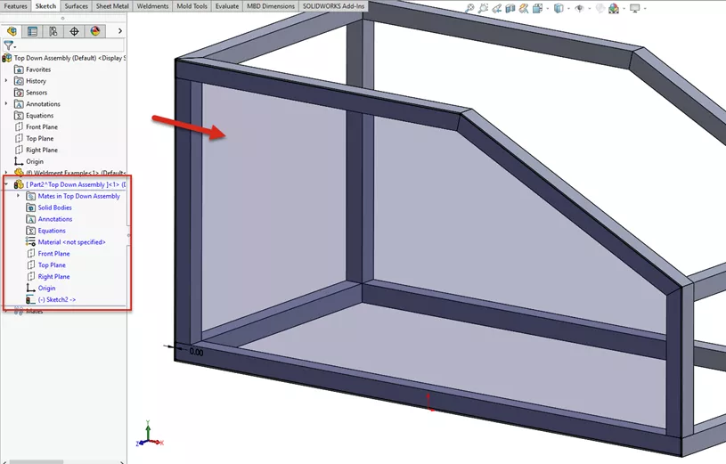
Figure 4: Utilize Offset Entities command to offset the outer edge of the tubes 1/8” (0.125”) in the direction shown. Note the finished sketch is Shaded, indicating a Closed Sketch Contour
Next, switch to the Sheet Metal tab in the CommandManager toolbar and select Base Flange/Tab. (Figure 5) Select the desired Sheet Metal options (thickness, k-factor, etc.) and click OK to complete the feature.
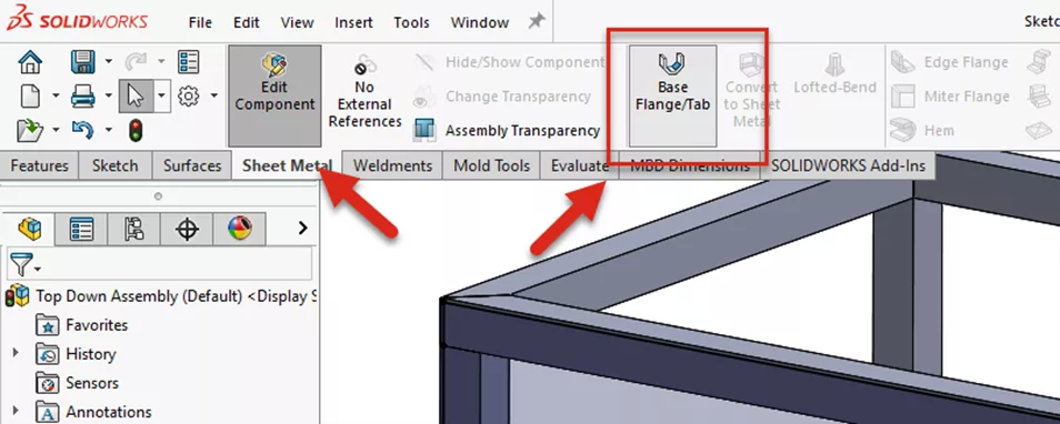
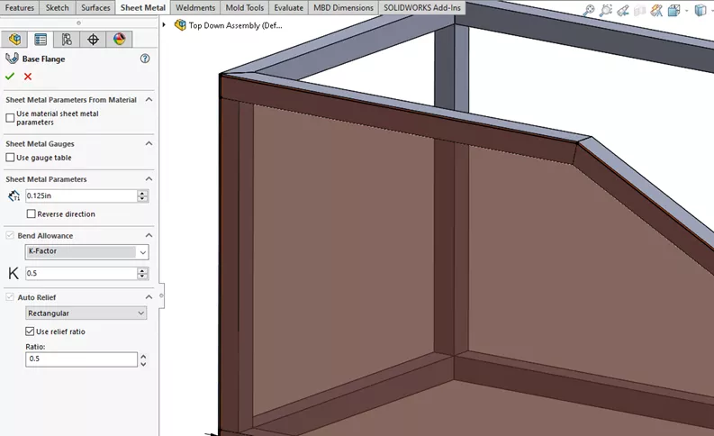
Figure 5: Using the Base Flange Sheet Metal feature, use the Sketch to create a 1/8” (0.125”) thick Sheet Metal Feature
The new Sheet Metal part has been created matching the shape of the Weldment tube structure.
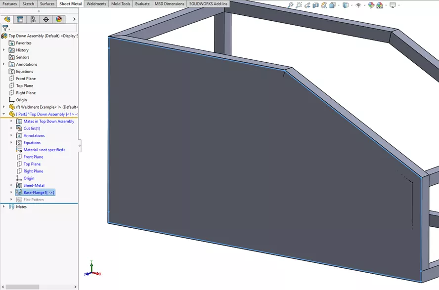
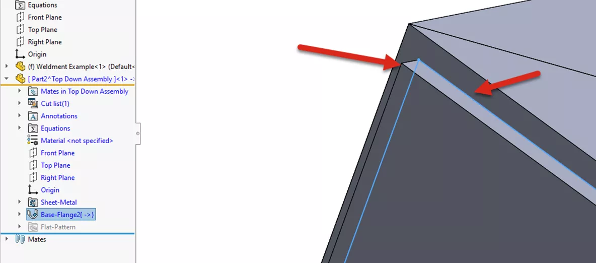
Figure 6: Sheet Metal Feature complete, matching the shape of the Weldment. Note the uniform offset of the Sheet Metal Feature from the outer edge of the Weldment tubes
Since the design intent is to have identical panels on both sides of the Assembly, we will select the Mirror Components feature from the Assembly CommandManager toolbar. (Figure 7)
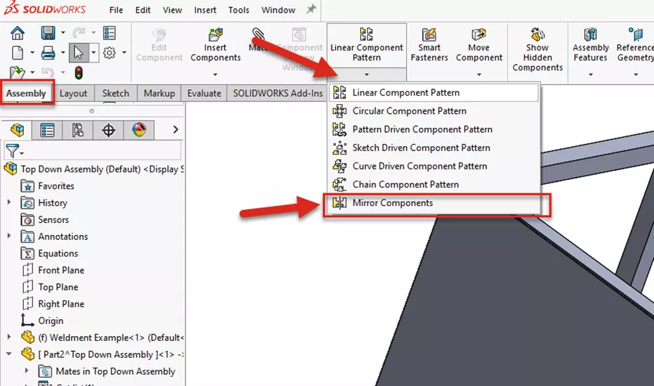
Select the Mirror Components command
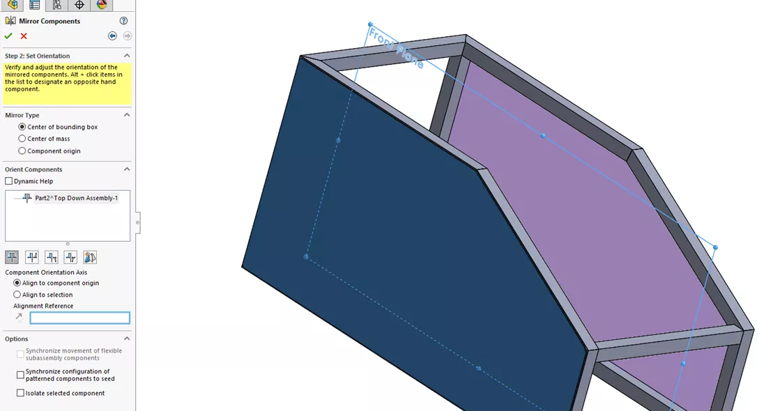
Select the body to be mirrored and the plane to use
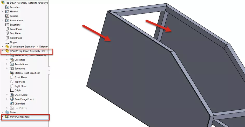
Figure 7: Optional use of the Mirror Components Command to create additional Sheet Metal panels
Because the side panels are driven by the edges of the Weldment Tubes, any changes to the shape of the Weldment will carry through to the Sheet Metal panels. ( Figure 8)
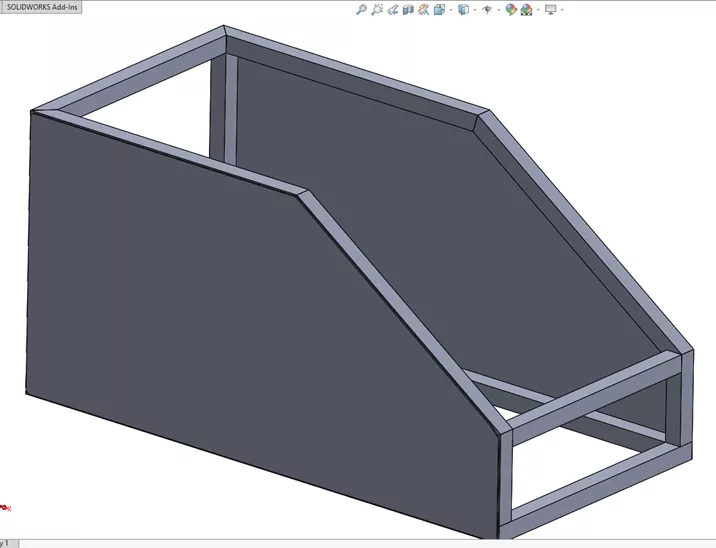
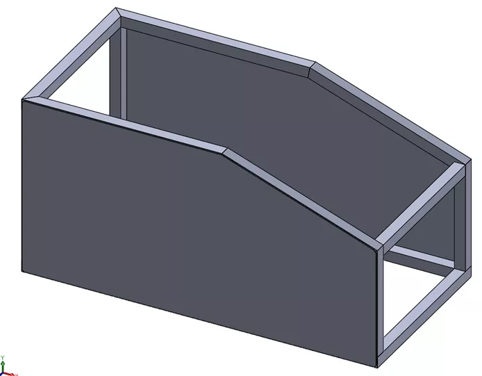
Figure 8: Note the side panels update with the change in angle of the Weldment Tubes
Saving Virtual Components
When you first save your new Assembly (Figure 9), you will be given two options:
- Save internally (inside the assembly) means the part file will not be found in a folder (Figure 10) and will only be visible when the parent Assembly file is open.
- Save externally (specify paths) will give you the option to save the part as a new file outside the Assembly.
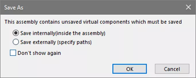
Figure 9: Save As options for Virtual Components
Figure 10: Component is stored inside the assembly
Benefits of Top-Down Assembly
As we demonstrated here, side panels were created inside the assembly. We didn’t need to create individual files prior to inserting them into the assembly, before adding mates and adjusting the shape of the panels to match the design of the weldment, as we would with Bottom-Up assembly methods.
The side panels can be easily adjusted by changing the shape of the weldment, ensuring that all parts update precisely. If the virtual file isn’t going to be used for any other assembly, the file can be saved internally in the parent assembly.
Drawbacks of Top-Down Assembly (saving external files)
Since the part was created within the parent assembly, changes to the Part File must be done in the context of the parent assembly. That is why Top-Down Assembly methods should be considered mostly for preliminary design work. Once the design has been finalized, consider opening the file that contains external references and fully define the features and sketches.
Want to Become an Expert?
The official SOLIDWORKS Assembly Modeling training course builds upon the Essentials lessons to provide instruction on advanced features and capabilities in SOLIDWORKS.
More SOLIDWORKS Tutorials
Create a SOLIDWORKS Assembly from a Multibody Part
How to Save a SOLIDWORKS Assembly as an STL File
Save SOLIDWORKS Assembly as Part and Preserve Geometry References
7 Ways to Improve SOLIDWORKS Large Assembly & Drawing Performance
![]()
About GoEngineer
GoEngineer delivers software, technology, and expertise that enable companies to unlock design innovation and deliver better products faster. With more than 40 years of experience and tens of thousands of customers in high tech, medical, machine design, energy and other industries, GoEngineer provides best-in-class design solutions from SOLIDWORKS CAD, Stratasys 3D printing, Creaform & Artec 3D scanning, CAMWorks, PLM, and more
Get our wide array of technical resources delivered right to your inbox.
Unsubscribe at any time.