SOLIDWORKS Backyard Design Project
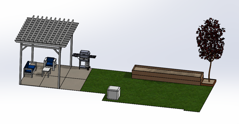
When I decided to redo my backyard, there were a few goals I wanted to accomplish: pour more concrete, replace the grass, and build a garden box. So, I started modeling my design plans in SOLIDWORKS.
My initial goal was to confirm how much space there was to incorporate the new features and then determine where to place them - but I was able to use my model for much more than that!
Current Backyard Setup
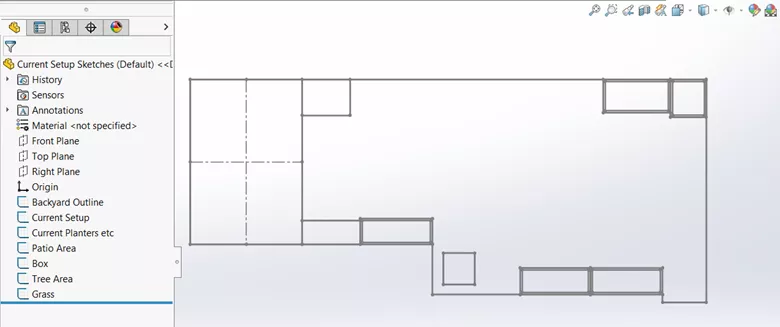
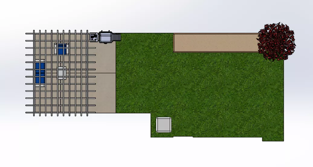
I started by modeling my current setup, which included concrete, grass, a pergola, a few smaller garden beds, and some other random items. I modeled the entirety of the yard in one sketch and then used that sketch as a base to get everything else modeled.
Then, I measured everything in the backyard and created separate sketches for each of the areas.
From there, I Saved a separate file corresponding to each sketch to create the different areas of the yard. This was especially helpful with the placement of each area when it got to the assembly level - I didn’t need to mate anything.
Most items were relatively simple to model, but for the pergola there were a couple different ways this could be done.
Pergola
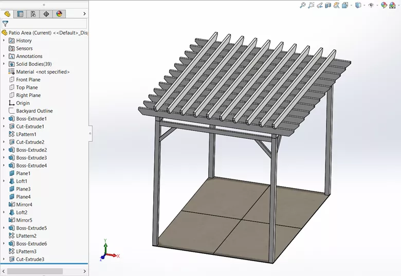
I initially thought using Weldments would be best, so I started by creating a 3D Sketch. But after a bit of time trying to get the precise placement of the lines, I found that, because of the different layers on the top of the pergola and different beam sizes, it was going to take a bit more planning and measurements to get it exact.
I would also need to make my own custom profile sizes to add to the Weldment library and add extra features to trim the ends.
Instead, I decided to try the other method of extruding the beams and using patterns to get it set up. This method was much quicker.
Note: Weldments is a very handy tool for certain applications, and although it seemed like it would be useful in this scenario, it wasn’t the most efficient for me.
Final Setup Configurations
The main goal of this project was to figure out where everything would fit and look the best, plus how much extra concrete to pour and the location and size of the garden beds.
Additional Concrete for Patio
For the concrete, it was important that the smoker fit in the space and to open up under the pergola for additional seating. I represented the patio set and smoker with some example files I found online, which helped me better visualize how much space and concrete was needed.
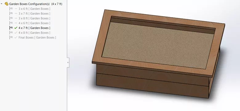
Garden Boxes
Since there isn't a ton of space in the yard, the biggest challenge was determining how big to make the garden bed and where to place it. I wanted it big enough to fit a lot of veggies, but not too big to where it takes up too much yard space.
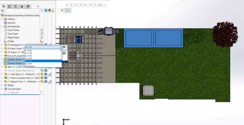
For the garden box model, I decided to create a few configurations to represent different possible sizes.
Once complete, I created a few different configurations at the assembly level as possible placements of the boxes.
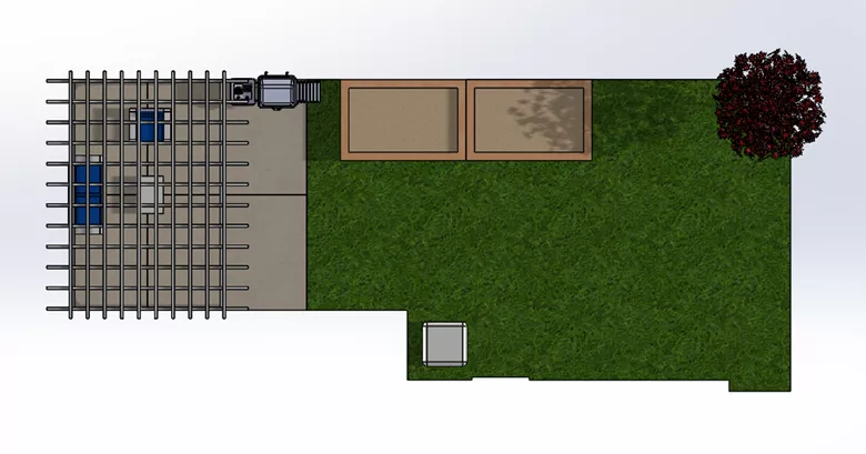
Setup 1:
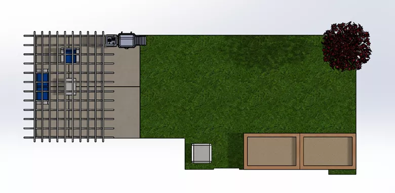
Setup 2:
Setup 3:
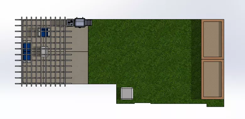
And in each of the configurations, to test out what the different sized boxes would look like in each location, I was able to easily change which configuration of the boxes I pulled.
Something I did not take into account is where in the backyard we get the most sunlight. So, I decided to go with a location for the boxes that was similar to Setup 1 but closer to the back corner with the tree.
Final Setup:
Other Uses of the Model
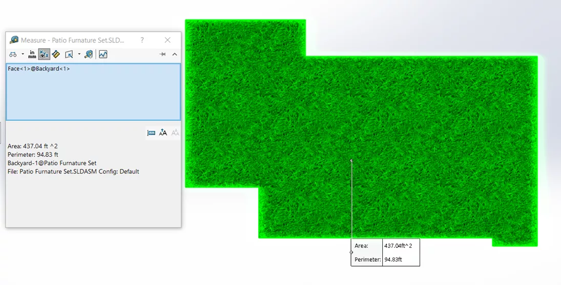
I was also able to use the model to measure the area of the yard where the new grass would be and to order the correct amount of topsoil and sod.
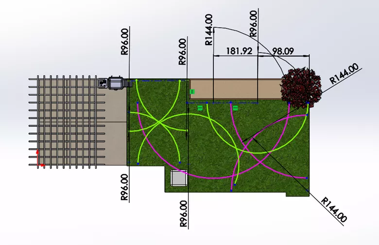
I used my sketches to help decide which sprinkler sizes would be best and that would cover all the grass. I simply created the sketch at the top-level assembly and used arc sketches to test the different sizes. I color-coded the 8' sprinklers green and the 12' sprinklers pink using the Line Format tool (for better clarity of the sketch).
I hope you found my SOLIDWORKS backyard design project inspiring! Check out more DIY SOLIDWORKS projects below.

SOLIDWORKS CAD Cheat Sheet
SHORTCUTS ⋅ MOUSE GESTURES ⋅ HOT KEYS
Our SOLIDWORKS CAD Cheat Sheet, featuring over 90 tips and tricks, will help speed up your process.
Related Articles
Designing a Trailer Using SOLIDWORKS Weldments
SOLIDWORKS at Home: DIY CAD Projects
Wonder Woman Costume Comes to Life with 3D Printing, 3D Scanning, and 3D Design

About Tashayla Openshaw
Tashayla Openshaw is a SOLIDWORKS Technical Support Engineer based out of our Headquarters in Salt Lake City, Utah. She earned her Bachelor’s degree in Mechanical Engineering from the University of Utah in 2018 and has been part of the GoEngineer family since February 2019.
Get our wide array of technical resources delivered right to your inbox.
Unsubscribe at any time.