SOLIDWORKS Electrical Terminal Block Connections
Displaying terminal connection names (how to change attributes)
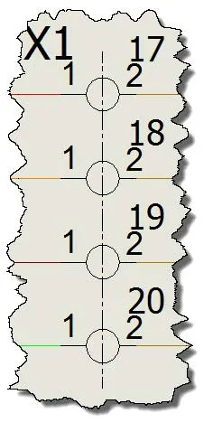
We are often asked about SOLIDWORKS Electrical best practices and the display of attributes has been one of the top questions regarding terminal strips. SOLIDWORKS has changed the behavior of their supplied terminals by updating its symbols to display connection names by default.
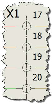
To change the attribute displayed before the symbol has been placed, you can edit the symbol and place, or remove the appropriate attributes you want to be displayed when that symbol is inserted into a schematic.
The question then becomes how do you change which attributes are displayed after the symbol has been placed. To answer that question, you have to decide as to whether is a change that you want to happen every time you place this symbol, or just for the symbol within the current schematic being edited?
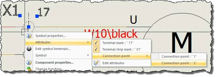
If it is a permanent change you can go back to your library and change it there then update the symbols. To change just what is displayed in the current scheme, right-click on the symbol and go to ‘Attributes’. From there available attributes are presented and the ones showing checks next to them are currently set to be displayed. To change the visibility, simply click on the attribute to toggle its visibility between shown or hidden. You can select multiple symbols to change a group of items.
If you select different types of symbols the attribute will appear as double quotes (“”); the double quotes will also appear if the attribute is available but currently empty.
Changing the orientation
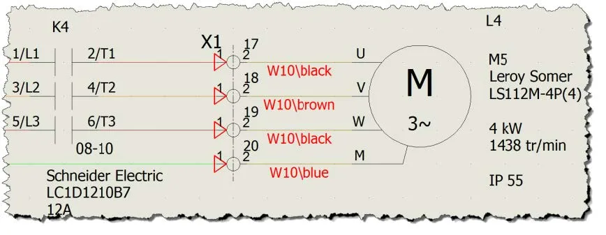
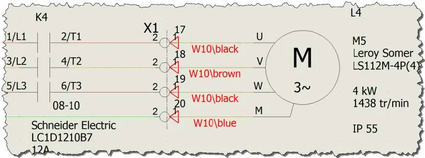
The orientation is another important factor when defining terminals in SOLIDWORKS Electrical as it defines the direction of the circuit or more specifically which side of the terminal the components are connected to. When placing a terminal or group of terminals you are present with a set of arrows. These arrows change with the type of component placed as the origin and destination, however they are displayed, the arrows will determine which component is on which side.
Below is a set of images that display the orientation arrows in both directions. The issue is what direction is correct for your placement and if needed how do you change the orientation after the terminals have been placed on the scheme.
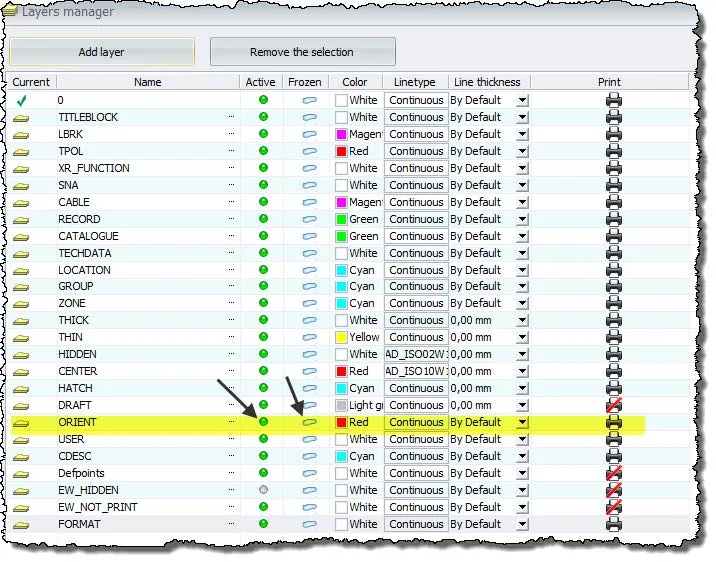
To view the arrows you have two options, the easiest is to start placement of a new terminal, this will display the orientation arrows, and the second option is to display and un-freeze the layer that the arrows are on. This will display the arrows until you hide the layer again.
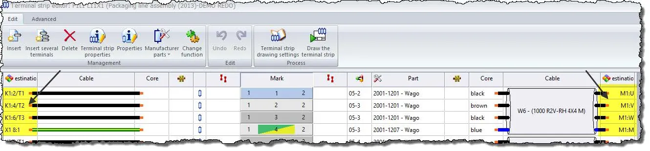
To verify the correct orientation you can edit the terminal strip by right-clicking on one of the terminals and selecting ‘Edit Terminal Strip’ or by editing the terminal strip through the “Project” tab and selecting “Terminal strips” and the appropriate terminal strip. Take note of the components on the left and right-hand sides. The component on the left will define the top (horizontally placed terminals) or left side (vertically placed terminals).
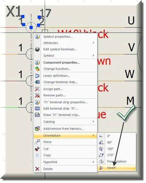
If you find that you need to ‘change’ the orientation of the terminals you can right-click on the terminal, one at a time, and choose the “Orientation -> Invert” command. This will change which component appears on the left or right side of the terminal.
Learn More About SOLIDWORKS Electrical
SOLIDWORKS Electrical Symbol Attributes
SOLIDWORKS Electrical Schematic: Displaying Alpha Numeric Rows & Columns
Inserting a Partial Connector in SOLIDWORKS Electrical
Creating and Inserting a Multi-Pin Connector in SOLIDWORKS Electrical
![]()
About GoEngineer
GoEngineer delivers software, technology, and expertise that enable companies to unlock design innovation and deliver better products faster. With more than 40 years of experience and tens of thousands of customers in high tech, medical, machine design, energy and other industries, GoEngineer provides best-in-class design solutions from SOLIDWORKS CAD, Stratasys 3D printing, Creaform & Artec 3D scanning, CAMWorks, PLM, and more
Get our wide array of technical resources delivered right to your inbox.
Unsubscribe at any time.