Creating and Inserting a Multi-Pin Connector in SOLIDWORKS Electrical
This article describes one method to insert a multi-pin connector in SOLIDWORKS Electrical Schematics.
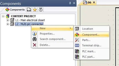
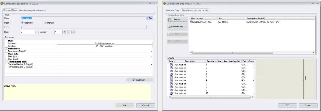
The first step is to create the connector in either the component tree or by placing a connector pin symbol on a scheme page in your project.
This set of images shows how to insert a component through the Component tree.
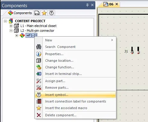
Once the component has been created or the first symbol has been placed into the scheme you can right-click on the component and select ‘Insert Symbol’, select the appropriate symbol and place it into your scheme. You will do this for the number of pins in your connector (in this example ten times).
Once you place your symbols, you may want to turn off the TAG attribute of the symbols. (In this example, I turn off the TAG attribute for symbols representing pins two through ten.)
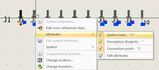
NOTE: When inserting the symbols, if you press the ‘thumbtack’ you can insert all the symbols in order without having to use the insert symbol command for each pin.
*If you want to show a partial connector (e.g., pins 1,2,4,6) insert four symbols and then modify which symbols represent specific pins in the Manufacture Parts tab of the symbol properties. I covered that in this article.
More SOLIDWORKS Electrical Tutorials
Inserting a Partial Connector in SOLIDWORKS Electrical
Easy Way to Add Watermarks in SOLIDWORKS Electrical
Why Won't My Wires Route in SOLIDWORKS Electrical? Part 1 & Part 2
![]()
About GoEngineer
GoEngineer delivers software, technology, and expertise that enable companies to unlock design innovation and deliver better products faster. With more than 40 years of experience and tens of thousands of customers in high tech, medical, machine design, energy and other industries, GoEngineer provides best-in-class design solutions from SOLIDWORKS CAD, Stratasys 3D printing, Creaform & Artec 3D scanning, CAMWorks, PLM, and more
Get our wide array of technical resources delivered right to your inbox.
Unsubscribe at any time.