SOLIDWORKS Flow Simulation Heat Pipes Explained
Heat Pipe is a feature available in the SOLIDWORKS Flow Simulation Electronic Cooling module that, as its name suggests, simulates heat pipes. Heat pipes efficiently transfer heat from a hotter surface to a colder surface using the principles of phase transition and conductivity.
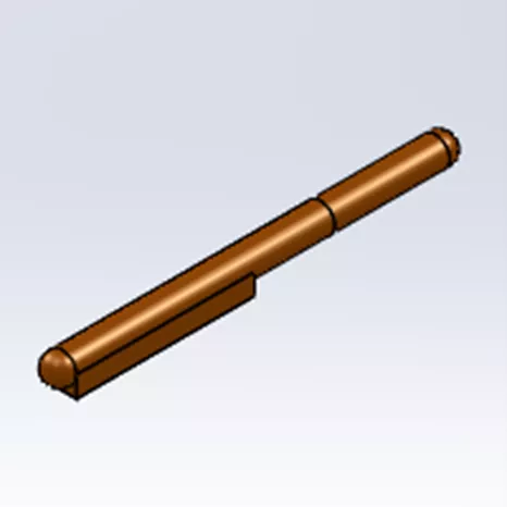
Figure 1: Solid heat pipe part
In SOLIDWORKS, heat pipes, as defined by the Heat Pipe feature, are solid components for which the heat conduction through them is determined by an Effect Thermal Resistance value set by the analyst.
![]() This article is a companion to this SOLIDWORKS Flow Simulation tutorial video.
This article is a companion to this SOLIDWORKS Flow Simulation tutorial video.
Adding a Heat Pipe to your Flow Simulation Study
In order to define a heat pipe in a SOLIDWORKS Flow Simulation project, check the box for Conduction in the Analysis Type tab of the General Settings dialog.
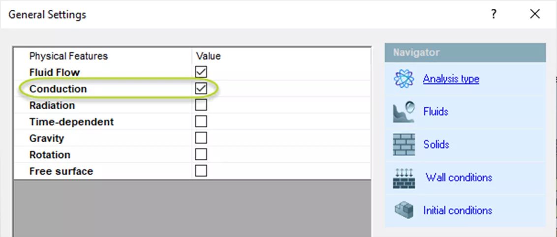
Figure 2: Analysis type tab of General Settings dialog
To insert a heat pipe, go to Tools > Flow Simulation > Insert > Heat Pipe. You can also find Heat Pipes listed under the Sources button in your Flow Simulation CommandManager tab.
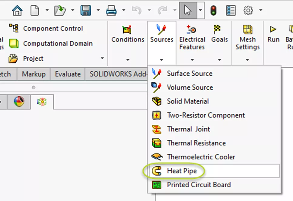
Figure 3: Sources dropdown in Flow Simulation CommandManager tab
If you’re planning to use the Heat Pipe feature frequently, you may want to add it as a line item to your Flow Simulation tree. To do this, right-click the name of your project and select Customize Tree. A list will appear from which you can toggle on and off different line items. With Heat Pipes listed in your tree, right-click it and select Insert Heat Pipe to create one.
In the first selection box in the Heat Pipe PropertyManager, select the component that will be acting as a heat pipe.
The next selection box is for the Heat In in faces.
In the third selection box, specify Heat Out faces.
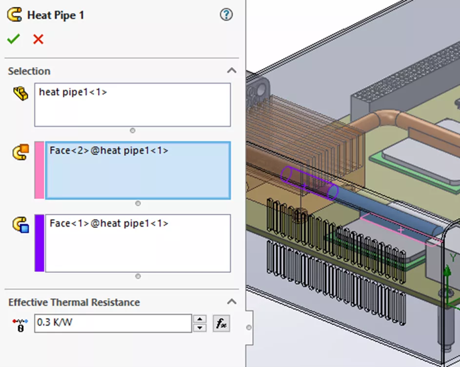
Figure 4: Heat Pipe PropertyManager
The final step is to enter the Effective Thermal Resistance factor - something that the analyst setting up the project needs to bring to the table. You can typically obtain this value from the manufacturer of your heat pipe or through experimentation. With your heat pipe defined, continue with setting up and running your study.
Flow Simulation Training
Want to become an expert? Consider sharpening your skills by taking the official SOLIDWORKS Flow Simulation Training course. Both in-person and online options are available.

More SOLIDWORKS Flow Simulation Tutorials
SOLIDWORKS Flow Simulation: Adding Local Mesh Control
SOLIDWORKS Flow Simulation FEA Load Transfer: Setup, Results, & Static Study
SOLIDWORKS Flow Simulation Recirculating System Scenario
SOLIDWORKS Flow Simulation Design of Experiments and Optimization Study
Fastest Way to Cool a Hot Dog: SOLIDWORKS Flow Simulation Study

About Lauren McGarry
Lauren McGarry is a Certified SOLIDWORKS Expert based out of San Diego, California. She earned her Bachelor of Science degree from Case Western Reserve University and has been with GoEngineer as a Technical Support Engineer since 2016.
Get our wide array of technical resources delivered right to your inbox.
Unsubscribe at any time.