SOLIDWORKS Flow Simulation: Adding Local Mesh Control
This guide explains adding a local mesh control in SOLIDWORKS Flow Simulation. When interpreting results, we want to ensure that the data is accurate by refining areas with a higher cell count. It is important to consider that only certain areas may need to be optimized, which can reduce the overall effort of adding too many cells. SOLIDWORKS Flow Simulation introduces several local mesh settings to help pick the appropriate settings.
Optimization Setup
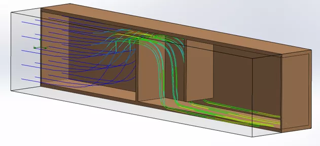
This example part demonstrates the change in velocity as the flow transverses through a narrow channel. Due to the substantial change in velocity, we will examine the default mesh plane to see if it can offer an accurate reporting of this velocity.
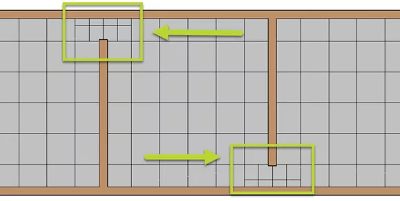
Currently, the mesh shows two cells between the solid and fluid. As a rule of thumb, we can optimize the results in this area by allowing 3-5 cells across the gap.
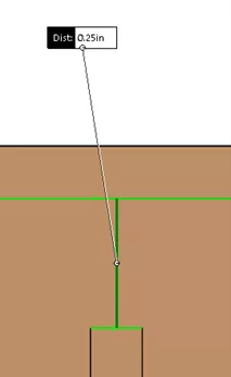
The next value to obtain is the model gap distance which should give the value on what flow considers a narrow channel.
Minimum Gap Size
Before creating a local mesh, one consideration is to define the minimum gap size in the global mesh parameters. This helps specify where channels are detected in the model (the gap between the solid and fluid).
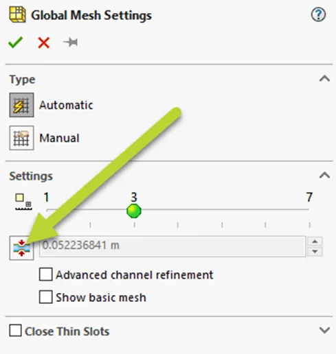
The default value is based on the model size, computational domain, and boundary conditions created in the study. If we choose to enter this value manually, we can review the mesh resolution later in our results to see the effects.
Adding Local Mesh Control
There are two options for adding a local mesh
- CommandManager: Mesh Settings > Local Mesh
- Study Tree: Right-click Mesh > Insert Local Mesh
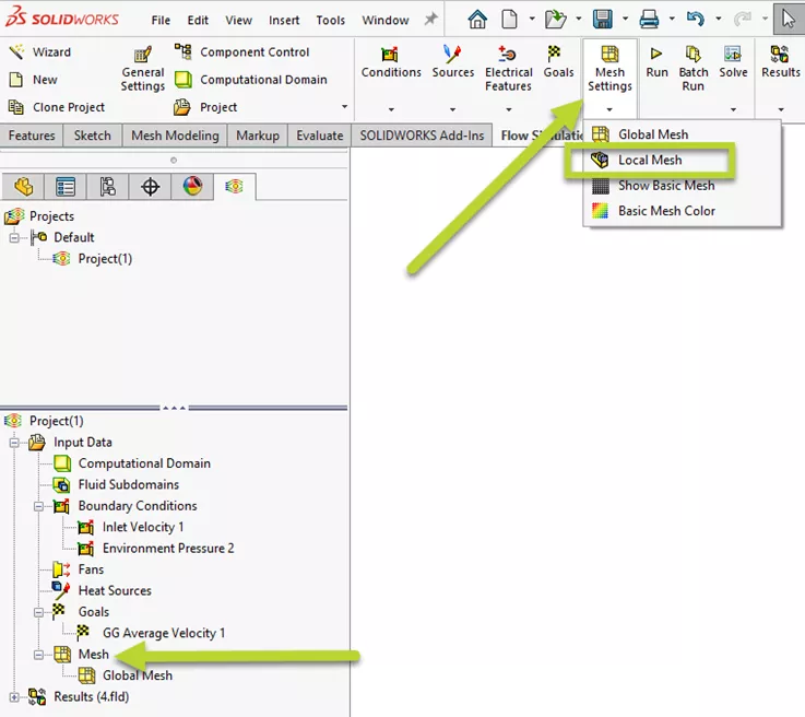
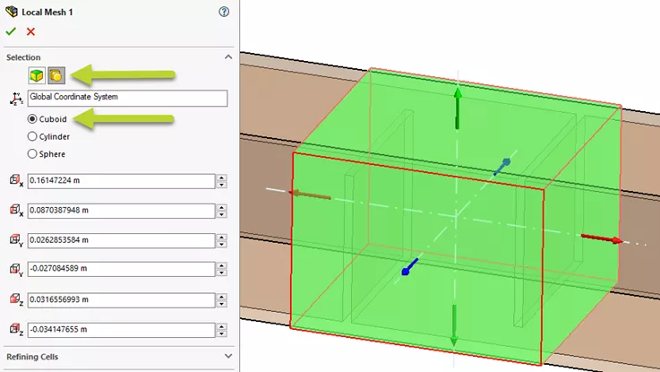
In newer versions of SOLIDWORKS Flow Simulation, two filters can be used for specifying the area:
- Solid body that encompasses the volume
- Adding a region based on a predefined shape
With either option, ensure the area covers the entire fluid boundary. In this example, we will pick the region filter with the cuboid shape. The area to capture will also surround the channels as needed.
Channel Settings
In the Channel settings, two main values can be entered:
- Characteristic Number of cells: With each level, the number of cells between the gap can be divided by half.
- Maximum Channel refinement level: The number of times the cells can be divided across the gap.
We will start by dividing the cell across the width.
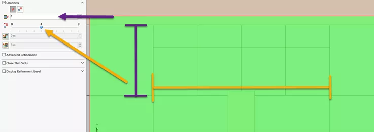
To increase the cells in the gap, we can adjust the characteristic level to a higher value.
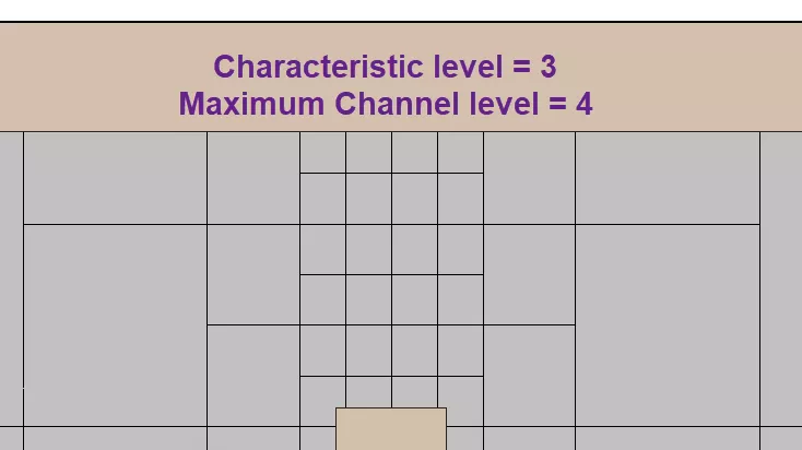
In flow, the number of cells grew exponentially. As shown above, we have reached our goal with the number of cells between the gaps.
Results
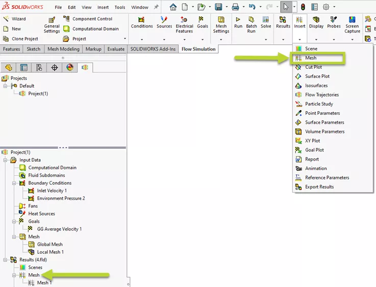
We can review the mesh by creating a mesh plot
- CommandManager: Insert > Mesh
- Study Tree: Under results, right-click Mesh > Insert
Using the options below, we can specify a plot based on all faces and colors based on the refinement level. The growth of the number of cells is indicated by the size of the cells getting smaller with each level of refinement.
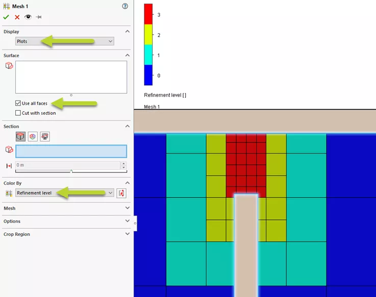
Based on this, each refinement level divides the cell by half in both width and height. With the SOLIDWORKS Flow Simulation local mesh settings, we have accomplished our goal of refining the cells across this region.
![]() Want to learn more? Check out this YouTube video for a detailed demonstration of adding mesh controls in SOLIDWORKS Flow Simulation.
Want to learn more? Check out this YouTube video for a detailed demonstration of adding mesh controls in SOLIDWORKS Flow Simulation.
More SOLIDWORKS Flow Simulation Tutorials
SOLIDWORKS Flow Simulation FEA Load Transfer: Setup, Results, & Static Study
SOLIDWORKS Simulation Solution Adaptive Mesh Refinement
SOLIDWORKS Flow Simulation Design of Experiments and Optimization Study
SOLIDWORKS Flow Simulation Sliding Mesh Explained

About Jackie Yip
Jackie Yip is a Technical Support Engineer at GoEngineer. When Jackie isn’t assisting customers or teaching a SOLIDWORKS Essentials class, he enjoys road biking and keeping up on the latest tech trends.
Get our wide array of technical resources delivered right to your inbox.
Unsubscribe at any time.