SOLIDWORKS Impact from Beginning to End
What happens when your product (or parts within it) collide with each other, with the ground, with a flying object? It’s a huge deal for quality and safety alike, so virtual testing (i.e., impact finite element analysis (FEA)) is an extremely important step of the engineering process. To do this kind of sophisticated analysis, you need an FEA software tool that matches both your product complexity and your budget. This article will review the spectrum of FEA tools in the SOLIDWORKS ecosystem with a focus on the impact simulation use case, so that you can better understand your options and make the right choice.

What Happens when Impact Occurs?
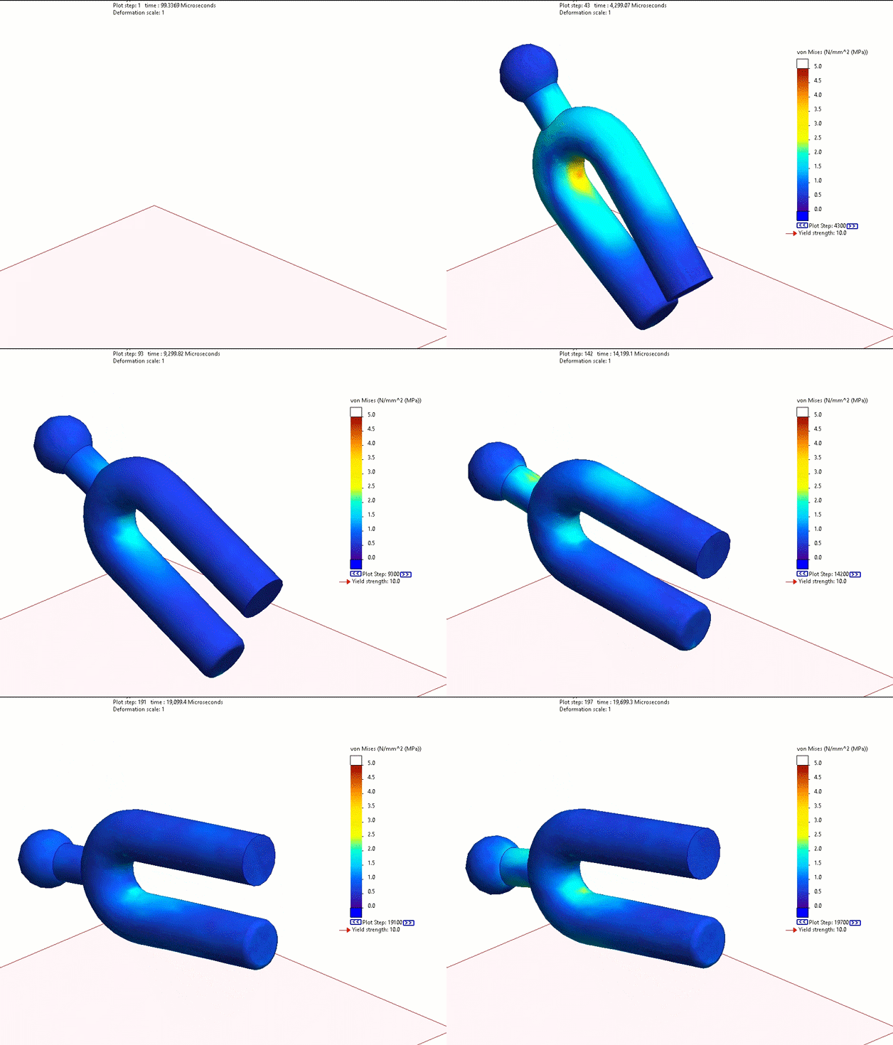
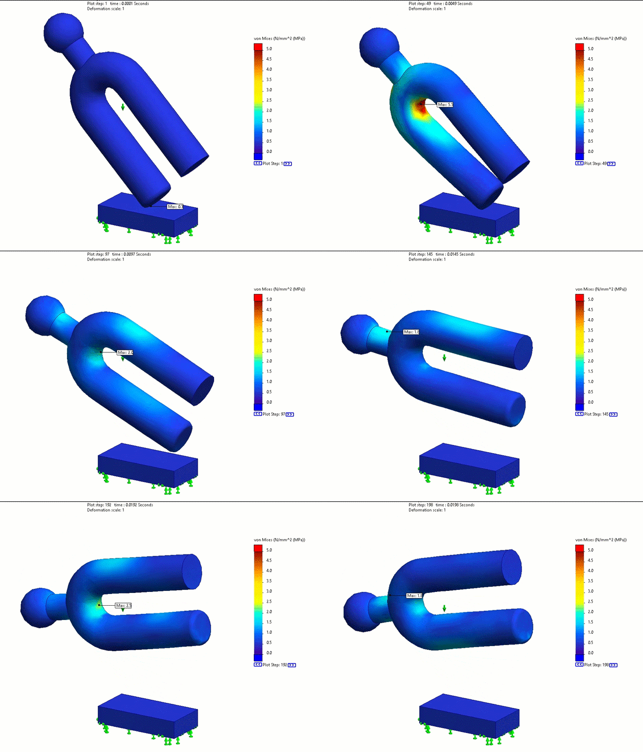
First, let’s talk about the theory of elastic wave generation. When an object undergoes impact, an elastic wave is generated that spreads through the geometry, starting at the impact location, like water waves spreading out from a rock being thrown into a body of water. Mass and stiffness are two properties of the material that make up the device undergoing impact that affect the speed and frequency of the elastic wave that is generated by impact (illustrated in the animation below). Three different simulation programs show that the elastic wave propagation through the impacting tuning fork is essentially the same because the mass distribution and stiffness are the same between the three programs.

SOLIDWORKS Drop Test, SOLIDWORKS Nonlinear Dynamics, and Analysis Abaqus
Basically, when it comes to a vibratory event like impact analysis, how much mass and its distribution, as well as the stiffness of the material that makes up the device undergoing impact, are going to play a pivotal role in the creation and how any elastic wave travels through the design.
Understanding the interplay between these two properties is essential to understanding impacts and the results that are given to you by the simulation software you are using. For instance, take the simplest model possible when it comes to studying vibrational events. The simple 1 degree of freedom (DOF) mass spring. Where all the mass is assumed to be in the block and all the stiffness is assumed to be in the spring. Understanding this simulation will help us better understand real-world impact events. Below is an animation of a bar impacting a wall, and how a series of 1 DOF models can help us to understand how the elastic wave travels through the bar.


Now that we have an idea of what happens at impact, let’s compare the programs that can be used to analyze impacts.
Comparing SOLIDWORKS Simulation Impact Tools
When reviewing different simulation software and how they deal with impact analysis, we will start at the bottom of the ladder and work our way up.

Impact Using SOLIDWORKS SimulationXpress
SOLIDWORKS SimulationXpress only works on single-body parts and cannot perform impact analyses directly. This tool is linear, so it can only apply a constant force. As a consequence of these limitations, the best it can do for the user is estimate impact on a single body and analyze bending stiffness. To estimate the stiffness, the user can use the known force load as well as the displacement output from SimulationXpress to calculate the stiffness of the part using this formula.
Stiffness (k) = Force (F) / Displacement (d)
With this formula and an Excel spreadsheet, we can pretend our tuning fork is a 1 degree of freedom (DOF) oscillator and estimate the force needed to displace the tuning fork the correct amount, and thus, arrive at the correct stress and location of the maximum stress after an impact of this tuning fork.
The main weaknesses of SimulationXpress are that it cannot simulate multibody parts or assemblies and that it can only apply forces and pressures. Finite element modeling options are also limited. Basically, you can use SOLIDWORKS SimulationXpress to get an “educated guess” as to the displacements, stress magnitudes, and peak stress locations from an impact, but if you are willing to purchase a higher-level software, you can do far more than just “guess”, as you will see.

Impact Using SOLIDWORKS Simulation Standard
If you have access to SOLIDWORKS Simulation Standard, you can do motion simulations and linear static simulations. Let's look at motion analysis first. In SOLIDWORKS Motion, you can solve for rigid body kinematics, meaning the tuning fork will be dropped but will not deform. Because the tuning fork is rigid, we cannot find details like stress and strain. We can find other variables, like the maximum force of the impact and the time it takes to fall all the way to the ground from a given height. This will help us make better assessments of the stresses in the higher simulations we will be performing on this tuning fork.

In Linear Static analyses, we can involve some nonlinearities into the simulation, like contact and geometry nonlinearities from large displacements. However, we are still limited in material nonlinearities and some geometric nonlinearities. So, we can use this static analysis to find stresses, displacements, strains, stiffnesses, etc., but only to the yield point of the material.
This will allow a designer to find the location of the max stress and determine if that max stress goes over the yield point of the material. If it does, then that means that changes to the geometry should be made in order to lower the max stress to below the yield point. SOLIDWORKS’ Linear Static analysis allows you to make as many changes and run as many simulations as necessary to improve your design to a point where it is no longer reaching yield stress at impact anywhere in the design.

Impact Using SOLIDWORKS Simulation Professional
Drop Test analysis is a tool included with SOLIDWORKS Simulation Professional, and with it, you can simulate dropped or thrown objects, like this tuning fork, either from a specific height or going at a specific velocity when the object hits the ground or other rigid surface.
The Drop Test is a nonlinear time-stepping solver that mimics real-world impact conditions. With the drop test, we can drop the tuning fork like in the motion analysis and still see it deform due to the strike and elastic wave that propagates through the design afterwards. You can also see the max stress without any additional force loads or spreadsheets like we had to use alongside SimulationXpress.
SOLIDWORKS Drop Test allows rigid body motion and physically shows the drop (like with SOLIDWORKS Motion) and allows deflection (like with SOLIDWORKS Linear Static). You get the best of both programs with a lot less setup required to obtain results. The drawback to this analysis type is that it is computationally intensive and can occupy significant computer resources for a long stretch of time. Because of this, it is generally recommended to only use very simplified models in a Drop Test. If you need to drop more complex models, there are more sophisticated software options that, when correctly configured, can do superior analyses in a similar amount of time.


Impact Using SOLIDWORKS Simulation Premium
The next level up is SOLIDWORKS Simulation Premium, which includes three different impact analysis tools; two of which are in the Linear Dynamics category, namely the modal time history and the response spectrum analysis. Unlike SOLIDWORKS Linear Static, Linear Dynamics is truly and completely linear. Any simulation done with these tools can permit no contact between parts and no large displacement. However, because we are compromising all our nonlinear capabilities, the computations are lightning fast.
Modal Time History analysis in SOLIDWORKS Simulation allows you to study how a vibratory event affects your design over time. It calculates stresses, displacements, strains, accelerations, and other results directly from time-domain input. To do this analysis with an impact scenario where contact cannot be modeled directly, you can combine a Drop Test study with a Modal Time History analysis. A simplified CAD model can first be analyzed in the Drop Test study to estimate impact forces. These force results are then applied in the full CAD model in a Modal Time History study. This workflow lets you capture fine geometric details without making the simulation prohibitively complex.

Another linear dynamics option for impact loading is the Response Spectrum analysis. The key distinction is that Modal Time History uses time-domain input, while Response Spectrum requires the input to be converted into a frequency-based shock response spectrum. The advantage of Response Spectrum analysis is that it focuses on peak values over a given time period, which often produces clearer, less “noisy” results than a full Modal Time History curve.

Both approaches offer faster and more efficient ways to predict stresses, displacements, and accelerations under impact than a traditional Drop Test. They also support damping, which helps reduce chaotic response behavior, an option not available in Drop Test studies.
The nonlinear option, which can also solve this problem in SOLIDWORKS Simulation Premium, is called nonlinear dynamics. In this option, we can apply an initial velocity of the tuning fork that equals the velocity it is going when it hits the ground after being dropped. The contact as it hits the ground, and all other nonlinearities, can be accounted for in this simulation. It can show the stress past yield in the plastic region and large deformations, as well as the elastic wave as it travels through the material of the tuning fork. The main drawback of running a nonlinear dynamics impact analysis is that it is very time-consuming and computationally intensive to run with large results files that take up a lot of disk storage space. Because of this limitation, it is generally only recommended to use nonlinear analysis when the simulation has too many nonlinearities for the simulations discussed earlier in this article to handle. For example, if you need to know what is happening past the yield point of a material, then nonlinear analysis is a must.
Impact Using Abaqus or 3DEXPERIENCE STRUCTURAL
As we move on to the pinnacle of mechanical FEA software, beyond even SOLIDWORKS Premium’s capabilities, let’s look at Abaqus and the 3DEXPERIENCE STRUCTURAL simulation tools (which use Abaqus “under the hood” as their solver). This simulation software offers even more capabilities to help obtain accurate results in an impact analysis. Key amongst these capabilities is everything that makes it practical to simulate impact on an assembly or full product level – any number of parts connected, colliding, and separating, made of any material, with its behavior accurately simulated.
First, there is Abaqus’ general contact option, where a few button clicks can turn on automatic contact detection for the entire model, calculated at every increment over the course of the analysis. Rather than anticipating and configuring every potential contact pair interaction before the analysis, which can be very time-consuming (and inaccurate) in any FEA software, it is all handled for the user by Abaqus/3DEXPERIENCE.
Abaqus also has extremely robust material modeling, accurately modeling materials after yield, undergoing progressive damage, hyperelastic behavior, time and temperature dependencies, and other complexities.
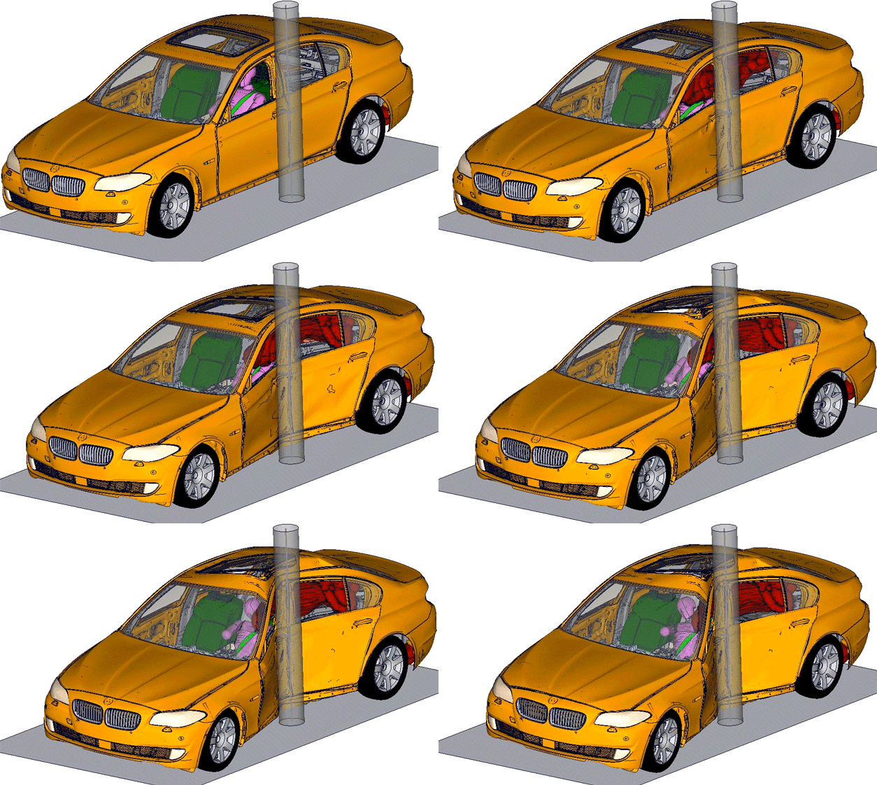
The Abaqus solvers also scale extremely well with parallel compute, effectively utilizing up to hundreds of CPU cores. There is even an official cloud compute service that any customer can purchase access to. For these reasons, an entire automobile impacting a pole can be simulated in Abaqus (but not in SOLIDWORKS Simulation).
Furthermore, Abaqus offers additional element features. One such feature is hex meshing, which more accurately captures high-frequency behaviors than the tetrahedral meshing that is available in SOLIDWORKS Simulation. Abaqus also offers damage and destruction behaviors in its elements. If something breaks or rips apart during impact, this high-level software can capture it.

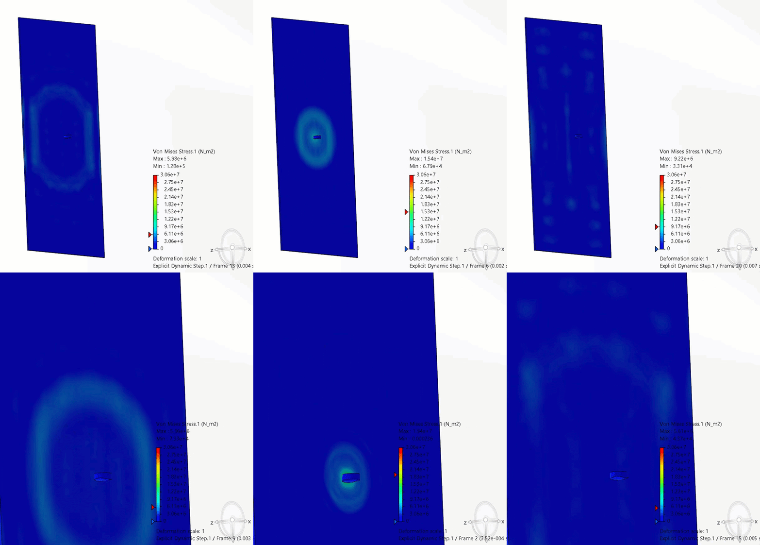
Basically, if the object you are simulating hits at an extremely high speed, like a bullet, or even as slow as a hockey puck striking plexiglass, you will need Abaqus to simulate it.
In essence, understanding impact behavior in structures involves a blend of fundamental principles and advanced simulation tools. Whether using any of the SOLIDWORKS Simulation packages or the advanced Abaqus Unified FEA software, the goal is to accurately predict and mitigate the complex effects of impacts on the designs you intend to bring to market. These tools and methods ensure safer, more resilient designs that every designer and engineer wants to create.

Whether you’re interested in working with simulation for the first time or eager to help your engineers achieve their best, the team at GoEngineer is ready to work with you. Contact our team to learn more.
Related Articles
SOLIDWORKS Simulation 2026 - What's New
6 Tips for Accurate Elastomer Modeling in Abaqus
Stabilization Strategies for Nonlinear Static Abaqus Models
SOLIDWORKS Simulation Standard vs 3DEXPERIENCE Structural Designer
Comparing All SOLIDWORKS Simulation Packages: Basic to Advanced

About Taran Packer
Taran is a SOLIDWORKS Simulation Technical Support Specialist at GoEngineer. He has a Bachelor’s degree in Biomedical Engineering from the University of Utah. Taran enjoys learning about different tools in SOLIDWORKS Simulation, Flow Simulation, and Plastics.
Get our wide array of technical resources delivered right to your inbox.
Unsubscribe at any time.