SOLIDWORKS Motion Utilizing Design Studies to Evaluate What-If Scenarios
SOLIDWORKS Motion, included in SOLIDWORKS Premium , allows for evaluating the mechanical performance of a rigid body mechanism through simulating its operational movements. It allows for simulating the effect of forces, springs, dampers, gravity, component contacts, and bushings to effectively visualize and measure the kinematic and dynamic behavior of a system.
These outputs include displacements, velocities, accelerations, forces, etc. SOLIDWORKS 2012 introduced the capability of linking motion studies to a SOLIDWORKS Design Study. Multiple scenarios can be set up in a single interface to analyze the behavior of a mechanism under various loading conditions. This guide will make use of a ballistic pendulum mechanism to cover the steps of how to create a design study linked to a motion study.
Related Article >>
SOLIDWORKS Motion: A Tip for Handling Performance 'Hogs'
SOLIDWORKS Motion Setup
The first step is to set up a motion analysis to simulate the operational movements of a mechanism. SOLIDWORKS Motion uses assembly mates to limit the degrees of freedom of a mechanical system and specify its range of movement. Contact conditions, springs, and dampers can be created to help define the mechanisms of operational movements.
Motion can be applied to the mechanical system through motors, forces, gravity, or preloaded springs. A ballistic pendulum is used to measure a projectile’s momentum, from which it is possible to calculate velocity and kinetic energy. It is based on a dissipative collision where conservation of momentum is conserved, but conservation of energy cannot be invoked due to the conversion of kinetic energy into inaccessible forms such as internal energy.
The ballistic pendulum mechanism includes two separate mechanical systems, the firing mechanism, and the pendulum system. The measured height of the pendulum’s center of mass after projectile impact can be used to calculate the velocity of the pendulum based on its gravitational potential energy and then its momentum.
The premise of an inelastic collision is that the objects will stick together after impact, in the case of a ballistic pendulum mechanism where a bullet will penetrate into a pendulum’s body. SOLIDWORKS Motion will not allow for bodies to stick together after impact, but an inelastic collision with the absence of this behavior can be specified in a contact condition setup.
The example used consists of a simplified firing mechanism that includes a barrel, a firing disk, and a 9mm bullet. The pendulum system includes a pendulum rigidly mounted to an arm with the other end of the arm connected to a bracket allowing for only rotational movement. Gravity is applied in the vertical direction.
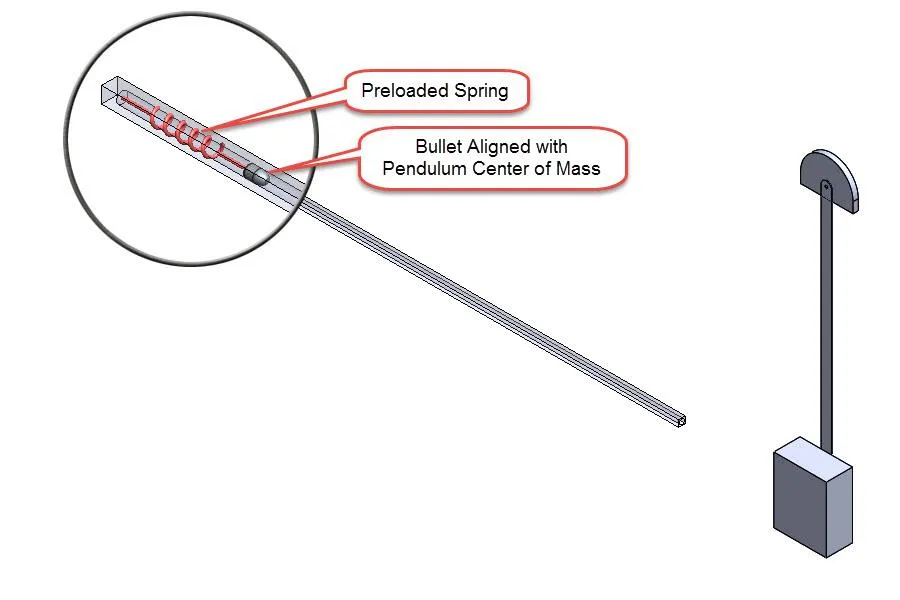
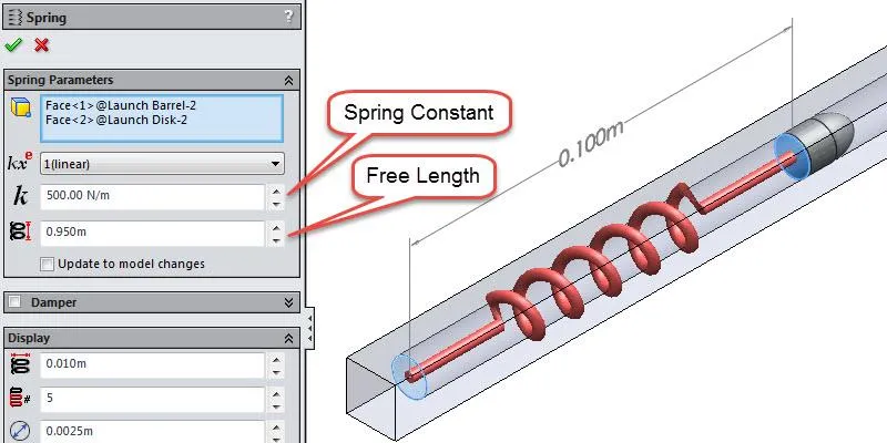
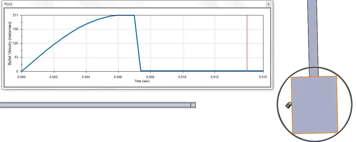
A preloaded spring connecting the firing disk to the barrel is used to set the bullet into motion. It is set up using a compressive preload. This is done by specifying the free length of the spring to be larger than the specified distance between the firing disk and barrel in the model. The bullet velocity can be adjusted by modifying the spring constant.
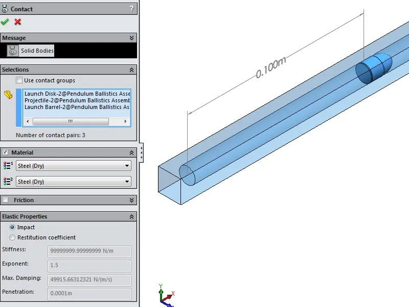
There are two contact conditions defined. One contact condition groups the barrel, firing disk, and bullet into one definition using a “Steel (Dry)” material condition for each selection. The material condition is used to automatically specify the friction and elastic properties of the collision. If the material conditions were specified differently, the order of selection does not influence the definition. Specifying a steel-rubber condition is the same as a rubber-steel condition.
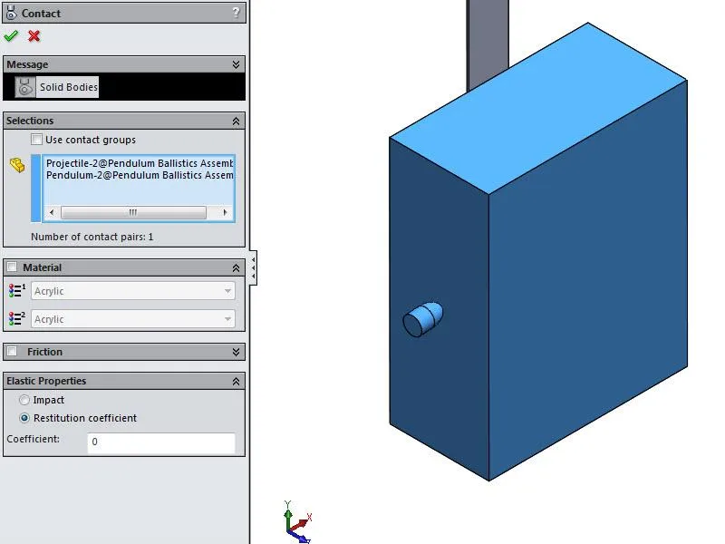
The other contact condition is defined between the bullet and pendulum. The material selection was not used for this condition and the elastic properties were manually defined. This can be done by either specifying impact parameters or a restitution coefficient. The restitution coefficient was set to zero to specify an inelastic collision. Specifying a value of one would result in a perfectly elastic condition. This would be representative of very rigid balls coming into contact (i.e. contact between balls in a game of pocket billiards). Friction was not enabled in either contact condition.
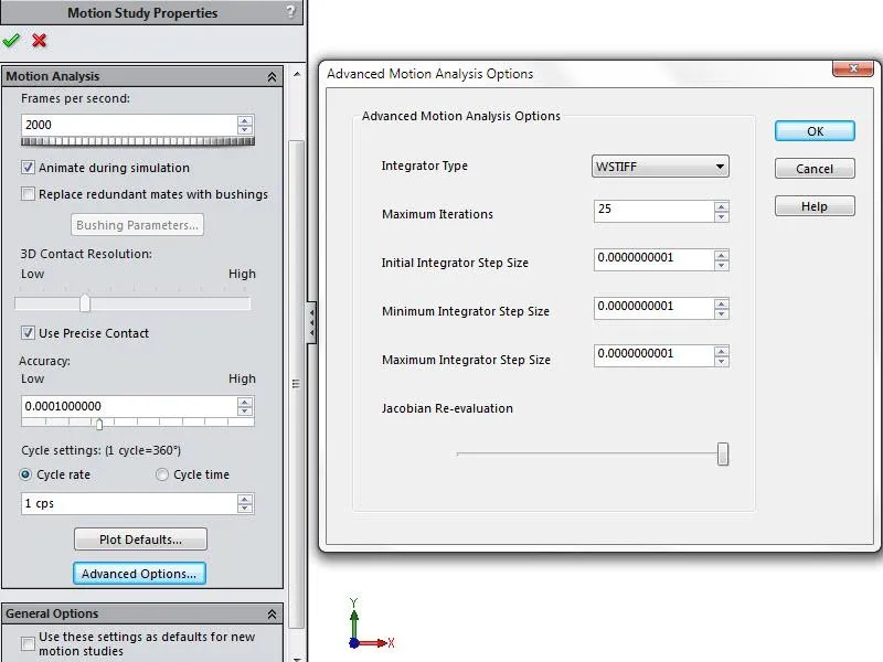
The motion study properties were modified to increase the resolution of the analysis. The “Frames per second” setting was modified from the default value of 25 to 2000 to properly resolve the dynamic behavior of the bullet and pendulum interaction. The “Use Precise Contact” option was selected to provide the highest resolution for the 3D contact analysis. The “Advanced Motion Analysis Options” were configured to ensure a successful analysis.
The integrator type was set to “WSTIFF”. This integration method was selected since it can adjust the step size used for the computation during the analysis to account for sudden step size changes induced by discontinuous forces, discontinuous motion, or abrupt events due to solid body contact. The integrator step sizes were also set to the lowest possible values.
Running the calculation with larger step sizes resulted in solution failure either at the beginning of the analysis when the bullet is set into motion or right after the bullet impacts the pendulum. Both of these failures are caused by abrupt changes in the step size used for the calculation.
SOLIDWORKS Motion Results
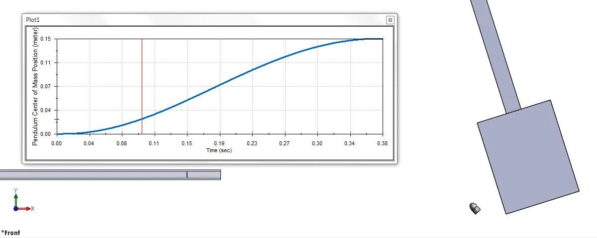
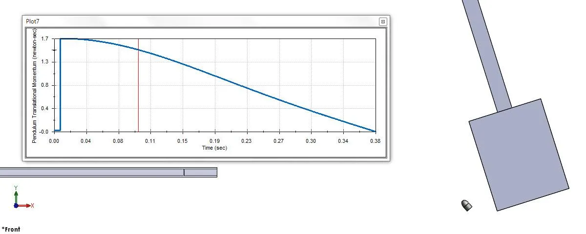
The main result output of interest for this study tracks the pendulum center of mass position in the direction of gravity (Y-Axis). This value can be used to manually calculate its velocity and momentum. The bullet’s momentum and velocity can then be calculated. These results can be accessed from within SOLIDWORKS Motion. A hand calculation can be performed to verify the validity of the setup.
A four-part tips and tricks video series going through the underlying equations and setup of a motion analysis simulating a ballistic pendulum is available on the GoEngineer website. A link to the first part of the video series can be accessed below.
Design Study Setup
A design study used to analyze what-if design scenarios requires two sets of conditions, variables (i.e. inputs) and constraints (i.e. outputs).
Variables can be tied to SOLIDWORKS Motion elements which consist of motor settings, action only, and action/reaction force and torque inputs, spring attributes, solid body contact friction, and elastic properties, etc.
Constraints are tied to sensors created from various motion result plots including displacements, velocities, accelerations, contact forces, momentum, kinetic energy, etc. The optimization option needs to be unchecked for a what-if design scenario. Leaving this option enabled allows for running a motion optimization calculation.
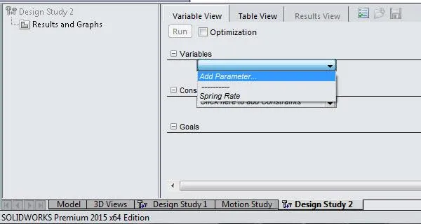
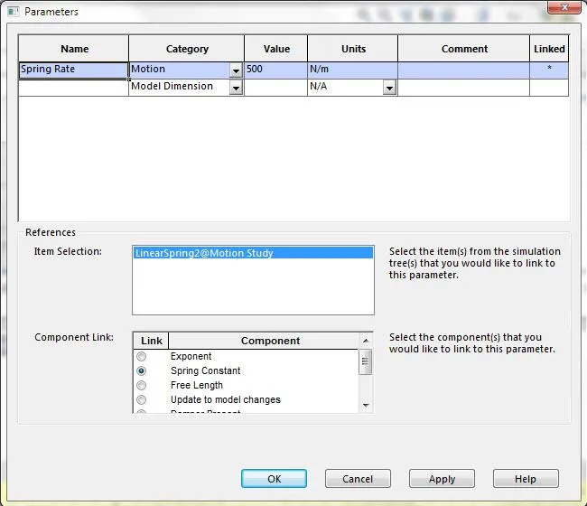
The variable definition window can be accessed by selecting the pull-down menu under variables and selecting “Add Parameter”. In the parameter definition window that pops up, the category can be changed to motion and a motion element can be selected from the motion analysis tree to create the link. A variable name and an initial value need to be specified. The ballistics pendulum example uses the preloaded spring constant as the input variable.
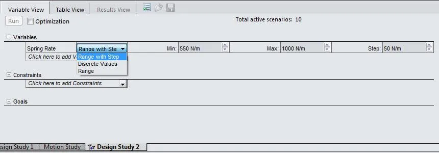
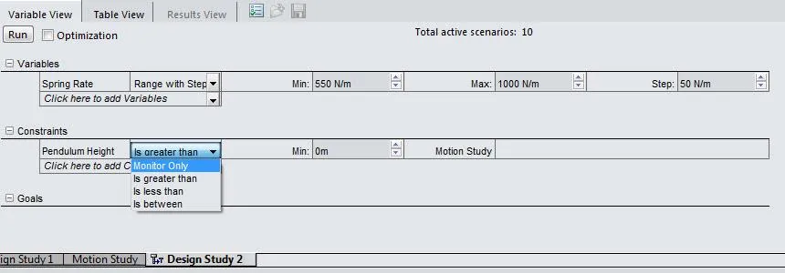
Once a variable is created, the bounds of its variance can be inputted in a couple of different ways for a what-if design study. Discrete values can be specified or the range with step option can be used to set the minimum, maximum, and step criteria. The range option is only used for optimization analysis. The ballistics pendulum example specifies a range of spring constants from 550 N/m to 1000 N/m with a step of 50 N/m. The design study is set up to evaluate changes in bullet velocity, pendulum center of mass position, pendulum momentum, contact forces developed between the bullet and pendulum during impact, etc.
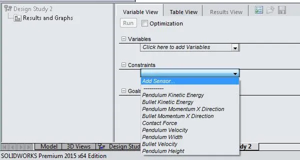
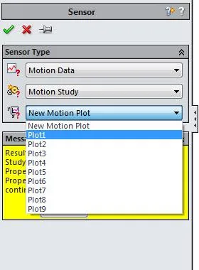
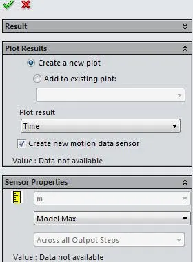
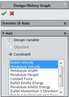
Constraints can be added by selecting the pull-down menu under constraints and selecting “Add Sensor.” Any existing motion sensors can be accessed from within the sensor property manager. Motion sensors are created from within the property manager of a motion result plot.
Once a sensor is added to a design study, the condition setting needs to be set to “Monitor Only,” for a what-if design study. The three other options are used for running an optimization analysis (is greater than, is less than, and is between).
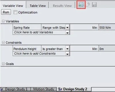
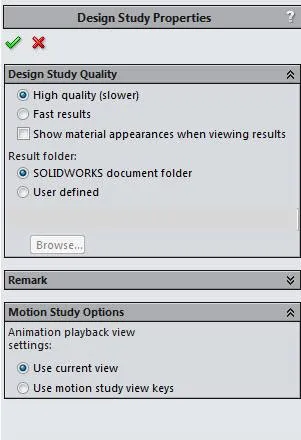
The what-if design study can be run using two different methods which can be accessed in the design study properties. The high-quality option will solve all defined scenarios. The fast results option will solve only a subset of the defined scenarios. It will solve the iterations tied to the extremes of the defined variable boundary and at the iteration tied to the variable’s median value. Linear interpolation is then used to calculate the results for the remaining defined scenarios.
Design Study Results
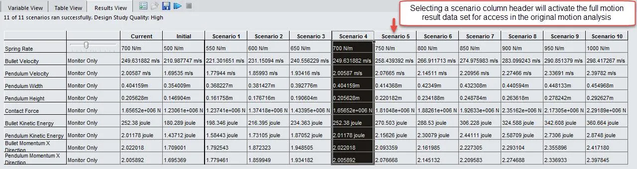
Results are listed in a table-based format in the design study interface. Full motion results are saved for each design iteration. Activating a scenario will load up the motion results tied to that specific scenario and in-depth post-processing can be performed by accessing the motion study. The following image depicts a high-quality result.
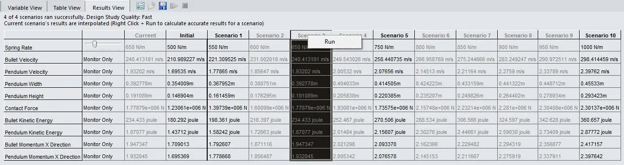
The results for a calculation run using the fast quality results option is depicted below. The scenarios which were calculated through linear interpolation are shown in a light grey font. The scenario columns displayed with black font represent scenarios with calculated results. Right-clicking at the top of a scenario column header allows for running a motion analysis for that specific scenario.
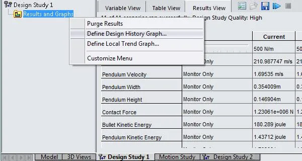
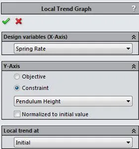
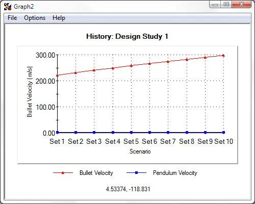
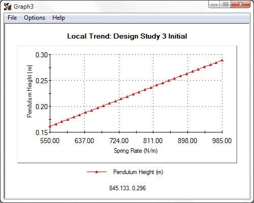
Right-clicking on the “Results and Graphs” link in the column to the left of the result table will provide options for deleting the results (Purge Results) or creating a Design History Graph (DHG) or Local Trend Graph (LTG). High-quality results allow for defining a DHG whereas fast quality results allow for defining an LTG. A DHG will plot out the design variable or specified constraints against the scenario instance. An LTG will plot out a specified constraint against the variable’s range of variance. If more than one variable is used in the design study, the “Local trend at” option is applicable and allows for specifying a specific iteration number. The selected variable will vary as mentioned above, but the other variables will remain locked at the values specified in the scenario set.
Benefits
- Allows for evaluating a large number of load cases without having to duplicate the motion study multiple times and manually changing the desired motion elements
- Intuitive interface with two different result quality selections allowing for trend comparisons or obtaining full calculated results
Expand Your SOLIDWORKS Skillset
How to Download SOLIDWORKS Block Libraries
Customizing the SOLIDWORKS Hole Callout File
SOLIDWORKS FeatureManager: Hidden/Forgotten Commands
![]()
About GoEngineer
GoEngineer delivers software, technology, and expertise that enable companies to unlock design innovation and deliver better products faster. With more than 40 years of experience and tens of thousands of customers in high tech, medical, machine design, energy and other industries, GoEngineer provides best-in-class design solutions from SOLIDWORKS CAD, Stratasys 3D printing, Creaform & Artec 3D scanning, CAMWorks, PLM, and more
Get our wide array of technical resources delivered right to your inbox.
Unsubscribe at any time.