SOLIDWORKS Plastics Frequently Asked Questions
These are the most frequently asked questions about SOLIDWORKS Plastics.
Question: Is SOLIDWORKS Plastics included in SOLIDWORKS Premium?
Answer: No, SOLIDWORKS Plastics is a separate product. It runs as an add-in on top of SOLIDWORKS Standard, Professional, or Premium.
Question: Is there an “Xpress” version of SOLIDWORKS Plastics?
Answer: There is no “Xpress” or light version of SOLIDWORKS Plastics. For a demonstration of SOLIDWORKS Plastics Professional or Premium, please contact your local SOLIDWORKS reseller.
Question: Where are SOLIDWORKS Plastics results saved?
Answer: SOLIDWORKS Plastics results are saved in a folder with the same name as the part, in the same directory as the part. If this folder is deleted, then the results will also be deleted.
Question: What are the key technical features of SOLIDWORKS Plastics?
Answer: SOLIDWORKS Plastics products are computer-aided engineering (CAE) simulation software tools that predict how melted plastic flows during the injection molding process – the manufacturing method used to produce more than 80% of all plastics products. The ability to predict how the plastic will flow allows the prediction of manufacturing-related defects. By predicting these defects, users can change part or mold geometry, processing conditions, or the plastic material to eliminate or minimize potential defects and save energy, natural resources, and time and money.
Question: Does SOLIDWORKS Plastics support multi-threading or multiple CPUs/ multi-core processors?
Answer: SOLIDWORKS Plastics supports multi-threading and takes advantage of multiple CPUs/ multi-core processors.
Question: Can SOLIDWORKS Plastics be used to analyze processes for non-polymer materials, such as Aluminum sand casting or injection of metals?
Answer: No, this is not recommended. The material input, governing equations/theory used by the solver, and result post-processing functionality in SOLIDWORKS Plastics are intended only for use with Polymers (commonly referred to as Plastics).
Even if the characteristics of a different material type (such as a metal) were approximated using the existing material behavior inputs that exist in SOLIDWORKS Plastics for polymers, there would be no expectation that results would be valid. Furthermore, the software specifically simulates the injection molding process, not other similar industry processes.
Question: What is the maximum number of injection points that can be applied in SOLIDWORKS Plastics?
Answer: There is an unlimited number of injection points that can be applied in SOLIDWORKS Plastics.
Question: What are the system requirements (supported operating system and hardware) for SOLIDWORKS Plastics?
Answer: Since SOLIDWORKS Plastics runs as an add-in within SOLIDWORKS, please see the system requirements for SOLIDWORKS:
http://www.SOLIDWORKS.com/sw/support/SystemRequirements.html
Additional recommendations for SOLIDWORKS Plastics:
- Core DUO or Quad-Core processor
- 4GB RAM for common plastic parts; at least 8GB RAM for complex or large parts
Question: Is there an explanation of the process of Venting (Venting Analysis) as it pertains to injection molding in SOLIDWORKS Plastics?
Answer: Venting is a natural process that occurs in the injection molding process. SOLIDWORKS Plastics software currently does not consider venting and therefore cannot provide venting analysis results.
Venting can easily be imagined and understand by visualizing air trapped inside the cavity of a closed mold. When the molten plastic material displaces the air inside the cavity, the air must be expelled ("Vented") to the atmosphere. If the air cannot be vented to the atmosphere, the "Dieseling" effect will occur.
Given this information, it’s important to note that SOLIDWORKS Plastics simulation assumes there is no air at all (a vacuum). Therefore, no air is displaced during a simulation, eliminating the need for Venting results. This also implies that the effect of air resistance at 14.7 psi (1.0 atm) will not be accounted for in a SOLIDWORKS Plastics calculation. This 14.7 psi can be neglected from the simulation results because injection pressures easily reach 10,000 psi, and 14.7 psi is negligible in comparison.
Question: Will SOLIDWORKS Plastics run in SOLIDWORKS 2012 SP2 or earlier versions?
Answer: SOLIDWORKS Plastics will run in SOLIDWORKS 2012 SP0 through SP2, but it is not supported. In SOLIDWORKS 2011 it is blocked with the message “SOLIDWORKS Plastics does not support your current version of SOLIDWORKS. Please install SOLIDWORKS 2012 SP3.0 or later.”
Question: Are Home Use Licenses (HUL) available for SOLIDWORKS Plastics?
Answer: No additional licenses of SOLIDWORKS Plastics are provided free of charge for installation on a second computer at home. The only option for running SOLIDWORKS Plastics on more than one computer is to use a floating license and borrow the license to the home computer or laptop.
Question: Why might there be more reported Weld Lines when using a smaller Triangle Size (mesh) in SOLIDWORKS Plastics?
Answer:
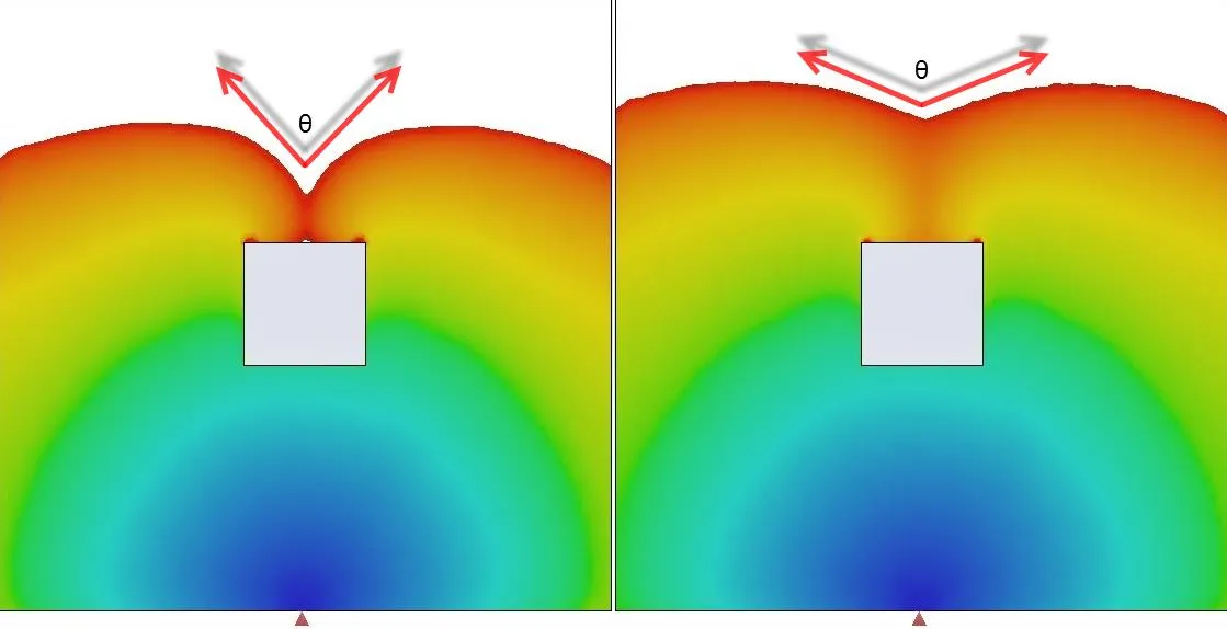
The Plastics Solver calculates the contact angle Theta (θ) of two melt fronts at every node. You can imagine that at a smaller Triangle Size (finer mesh), there are more potential nodes where the angle Theta (θ) can meet the requirements the solver uses to determine if a Weld Line will form.
To define the angle Theta (θ) in the Plastics software, you can change the value by performing the following:
After the mesh has been generated >> in the Plastics Property Manager, INPUT >> Process Parameters >> double-click Fill Settings >> expand the Advanced field >> Options >> change the value for Weld line face angle(90 ~ 150.)
Please also see SOLIDWORKS Solution ID: S-065747
When using a larger Triangle Size, there are fewer opportunities for the angle Theta (θ) to meet the set value for Weld line face angle (90 ~ 150.), which is why there are more reported Weld Lines at a finer mesh.
Question: Can SOLIDWORKS Plastics simulate Gas-Injection molding?
Answer: Yes, SOLIDWORKS Plastics can simulate gas injection molding.
To do so, you have to activate the Co-Injection option from the Flow Settings. If the second selected material is gas (Nitrogen), then the injection process becomes gas-assisted injection.
Nitrogen can be selected from the Polymer dialog box:
- Click the Set Coinjection button
- From the drop-down menu, select 2nd
- In the Plastic Databank tab, select the GAS category and the Nitrogen material.
This feature is supported only with a Solid mesh.
Question: Does SOLIDWORKS Plastics assume perfect venting of air in the mold cavity?
Answer: Yes. In SOLIDWORKS Plastics, venting is assumed to be ideal, meaning the plastic melt does not encounter any resistance due to the air in the mold cavity. This is a common assumption made by various Plastics and Mold analysis software packages.
Question: Is it possible to perform warpage analysis in SOLIDWORKS Plastics?
Answer: Warpage analysis can now be performed in SOLIDWORKS Plastics Premium.
Question: Can SOLIDWORKS Plastics network licenses be set up as TRIAD?
Answer: At this time SOLIDWORKS Plastics network licenses cannot be set up as TRIAD.
Question: Is it possible to do microchip encapsulation in SOLIDWORKS Plastics?
Answer: Microchip encapsulation molding analysis is currently not possible in SOLIDWORKS Plastics
Question: What is Gas-Injection molding?
Answer: Gas-injection molding has been developed to save material, shorten cycle times, and improve the surface aspects of thick-walled injection-molded parts. Gas-injection molding uses a standard injection-molding machine, extended with equipment to inject gas (normally Nitrogen) parallel or in series with the injection of the melt.
Gas-injection can take place through the same nozzle as the melt (machine nozzle), or via one or more special gas injection needles located at the runner or where there are material concentrations (thicker walls). Special machine nozzle designs are needed to ensure reliability.
The gas-injection molding process starts with the injection of plastic into the cavity (see Fig. 2 in attachments). When the cavity is 50-95% full (depending on the shape of the part – see Fig. 3), the barrel is closed by a “shut-off” and gas injection starts. It can be controlled by pressure or by volume. The gas expands in the cavity, pushing the plastic in front of it until the cavity is filled. Then the gas-pressure is reduced by withdrawing the injection nozzle from the sprue so that the gas can escape.
In some designs, the gas may be allowed to escape from the cavity via the injection needle, so that the machine can recover the gas for re-use. If the gas is injected through the same nozzle as the melt, a second injection of plastic is made to seal the hole in the part.
Question: Does SOLIDWORKS Plastics require advanced FEA training?
Answer: No. Unlike competitive products, SOLIDWORKS Plastics is not a tool for analysts requiring plastics domain expertise or knowledge of finite element meshing and solution techniques.
Question: Do all SOLIDWORKS Plastic products require a SOLIDWORKS license to run?
Answer: Yes. SOLIDWORKS Plastic are add-on products and they require SOLIDWORKS to run.
Question: What is Moldex3D/eDesign?
Answer: Moldex3D/eDesign is a suite of software that helps you to quickly check the manufacturability of injection molded plastic part design. This is developed by the SOLIDWORKS® Solution Partner Moldex3D and further information can be found on the following website:
http://www.moldex3d.com
Question: Can SOLIDWORKS Plastics be added to SOLIDWORKS stand-alone and network licenses?
Answer: Yes. They are add-on products ONLY and can be added to either stand-alone or network licenses.
Question: Why are the "Volumetric Shrinkage at End of Fill" and the "Sink Marks" results null for my SOLIDWORKS Plastics simulation?
Answer: The "Volumetric Shrinkage at End of Fill" and the "Sink Marks" results cannot be calculated when the selected polymer material has no PVT data. When the PVT data is defined as a constant, it only corresponds to a constant density (as a function of pressure and temperature). Therefore, the shrinkage and sink marks cannot then be simulated. SOLIDWORKS Plastics cannot provide PVT data for some materials when the manufacturers have not disclosed this data.
If you have this data, you can copy the existing material from the database, and then enter the PVT data into the copied custom material.
Question: What kind of user input is used for the SOLIDWORKS Plastics Cooling (Cool) Module and which study tree items are related to this type of analysis?
Answer: The primary Cooling module input is defined using Channel Design > Cooling Channel.
Please note that the Plastics study tree will show items related to Cooling module only when applicable (e.g. Input > Material > Coolant; Input > Process Parameters > Cool Settings; Input > Boundary Conditions > Cool Pipe; Run > Cool).
Question: Which types of stresses are taken into account by SOLIDWORKS Plastics Warp analysis?
Answer: The SOLIDWORKS Plastics Warp module takes into account three different types of stresses:
- Residual stress from pressure being applied then released
- - Thermal stresses caused by thermal contraction as the part cools
- - Gravity effect and self-weight (usually relatively smaller than residual stress)
Question: Which discretization method (e.g. Finite Element, Finite Volume, Boundary Element) does
SOLIDWORKS Plastics use for Shell and Solid mesh types?
Answer: The discretization method that SOLIDWORKS Plastics uses depends on both the type of mesh (Shell / Solid), and what type of analysis you are performing (Flow, Pack, Cool, or Warp).
Shell Mesh:
- Flow: Finite Element Method
- Pack: Finite Element Method
- Cool: Boundary Element Method
- Warp: Finite Element Method
Solid Mesh:
- Flow: Finite Volume Method
- Pack: Finite Volume Method
- Cool: Finite Volume Method
- Warp: Finite Element Method
Question: How can I pick the accurate position of the model to define a gate?
Answer: If you want to pick an accurate position of the model to define a gate, you need to create a 3D sketch point on the model. Then you can select this point as Gate Selection in SOLIDWORKS Plastics.
Question: What kind of solid mesh can I make in SOLIDWORKS Plastics?
Answer: Tetrahedron, prism, hexahedral and pyramidal shapes can be created in the meshing process.
Question: Is there any limitation on the aspect ratio of the solid mesh created by SOLIDWORKS Plastics?
Answer: The aspect ratio should not exceed 1000.
Question: Where would the potential burn marks caused by the Dieseling effect be found on an injection molded part?
Answer: The burn marks caused by the Dieseling effect will typically be found at the locations indicated by the Plastics result type "Air Traps".
SOLIDWORKS Plastics Property Manager >> RESULTS >> double-click Flow Results >> check the box for "Air Traps"
Question: Should a runner system be included in a SOLIDWORKS Plastics Warp analysis? If not, how can it be excluded?
Answer: This depends on whether the runner is broken off when the part is ejected. If the part undergoes cooling with the runner system still attached and the geometry is such that the runner system may contribute to the overall warpage of the part, then it should be included.
To exclude a runner system from Warp analysis, go to Boundary Conditions > Runner Element. In the dialog, it is possible to omit a runner from warpage calculations.
Question: How is the Inlet Melt Temperature in a SOLIDWORKS Plastics Advanced Cooling (Cool) Analysis determined?
Answer: By default, the Inlet Melt Temperature under Cool Settings > Process Parameters is applied by the software automatically based on material selection.
Expand Your SOLIDWORKS Plastics Skillset
SOLIDWORKS Plastics Premium 2021 Cooling Channel Mesh
How to Minimize Sink Marks in Ribs in SOLIDWORKS Plastics
Using SOLIDWORKS Plastics to Design Plastic Sample Kits | Customer Story
Get our wide array of technical resources delivered right to your inbox.
Unsubscribe at any time.