SOLIDWORKS Plastics: Weld Lines
SOLIDWORKS simulation tools can provide valuable feedback on your projects by simulating designs and manufacturing processes early in the development workflow. Using this feedback, designers can save considerable time and prevent costly redesigns that might have gone unnoticed until production started. SOLIDWORKS Plastics can help prevent common manufacturing and quality issues in injection molded parts such as weld lines. In this article, we’ll take a closer look at the causes of weld lines, their effects on quality, and how to prevent or mitigate them.
What Are Weld Lines?
Weld lines, sometimes referred to as flow lines or knit lines, are potential areas of weakness in an injection molded plastic part where two or more flow fronts meet and join together. Ideally, these flow fronts of melted plastic would meet and meld together, forming a solid bond and, at worst, are merely cosmetic defects. However, depending on the shot parameters being used and the mold design itself, weld lines can sometimes result in a bond that is weaker than the surrounding material, causing warping, defects, and mechanical failures.
Contributing Factors
Several factors influence the formation of weld lines, including:
- Geometry: The shape, complexity, and thickness of the part design. Areas with rapid changes in geometry, such as thin-walled sections like in the example later in the article, can cause the formation of weld lines.
- Material Choice: The properties of the chosen material can have a significant impact on the presence of weld lines. Some materials have better flow properties and are less prone to weld line formation.
- Injection Speed and Pressure: The injection speed and pressure have a significant impact on the flow properties. High injection speeds may cause cooling at the flow fronts, preventing proper bonding.
- Melt Temperature: Low melt temperatures can lead to inadequate bonds at the flow fronts, causing weld line formation.
- Mold Temperature: Like injection speed and pressure, mold temperature plays a significant role in the introduction of weld lines. Specifically, differences in temperature across the mold will cause differences in flow rates and the ability of two fronts to properly meet and bond.
- Mold design: Gate location can have a big impact on the formation of weld lines, but it can also be an effective way of mitigating the issue by choosing locations that push the flow fronts and their resulting weld lines to non-critical areas.
Mitigation and Elimination of Weld Lines
Depending on the design, it may not be possible to completely eliminate weld lines in an injection molded part. However, increasing melt temperature, adjusting injection speed, pressure, and cooling times as well as carefully choosing injection point locations can drastically improve results. Post-manufacturing processes such as heat treatment or surface finishing may help reduce the visibility and impact of weld lines.
Example
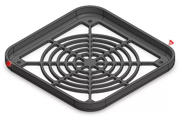
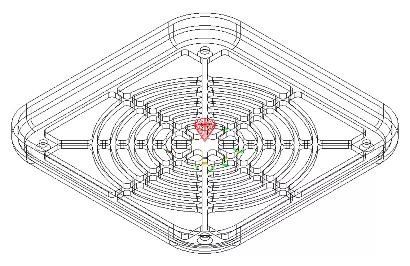
In the following example, a simple fan cover is being injection molded. The injection locations are on opposite sides near the corners of the part.
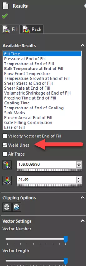
Using SOLIDWORKS Plastics, we can simulate our mold, injection parameters, and material properties to visualize where these weld lines will appear. The option to view weld lines is located in the Results PropertyManager.
After running the simulation and selecting the option to view the weld lines, we get the following result.
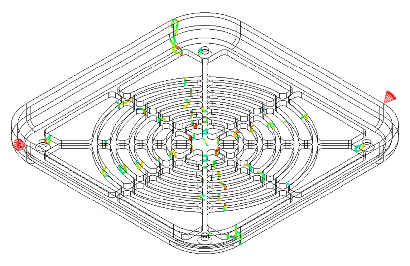
There are a large number of weld lines in the center where we have very thin features. Depending on the application of the part, this might lead to weakness in these features and potentially a failure.
With SOLIDWORKS Plastics, we can make quick changes to the location of the injection sites. In this case, we will change to a single injection point and place it in the center of the part.
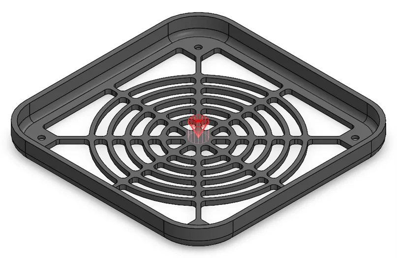
This will help to reduce the number of weld lines and push flow front issues to the edges of the part where it is sturdier.
After running the simulation again, we can see a significant reduction in the number of weld lines, resulting in a more robust part. Further changes to the mold temperature, material temperature, and injection parameters may result in even better part properties.
Conclusion
SOLIDWORKS Plastics and its other simulation tools can offer valuable insights early in your design process. While weld lines are a common issue in injection molded parts, understanding the factors that cause their formation can help to reduce their impact and help in producing high-quality, defect-free parts.
I hope you found this article helpful. Check out more SOLIDWORKS Simulation articles listed below. Additionally, join the GoEngineer Community to participate in the conversation, create forum posts, and answer questions from other SOLIDWORKS users.
More SOLIDWORKS Simulation Articles
SOLIDWORKS Flow Simulation Coefficient of Drag
Intro to Creating Lids in SOLIDWORKS Flow Simulation
Optimizing Your Workstation Budget for Design & Engineering Applications: Simulation
Computational Fluid Dynamics (CFD): Applications & Solutions
SOLIDWORKS Simulation Mesh Convergence in Frequency Analysis
![]()
About Chris Villeneuve
Chris Villeneuve is a SOLIDWORKS Technical Support Engineer at GoEngineer.
Get our wide array of technical resources delivered right to your inbox.
Unsubscribe at any time.