Computational Fluid Dynamics (CFD): Applications & Solutions
Computational fluid dynamics, or CFD, is essential to modern engineering in nearly every industry. Why does it matter? Where does it come from? What forms does it take and where do they apply? How can you take advantage of it? This brief introduction to CFD will answer these questions.
Table of Contents
- The Importance of Fluids
- Measurement and Flow Regulation Devices
- Wind Tunnels
- Virtual Simulation of Flow Fields
- Common CFD Methods
- Computational Cost/Benefit
- CFD Consulting Solutions
- SOLIDWORKS CFD Solutions
- 3DEXPERIENCE Platform CFD Solutions
- Dassault Systèmes Desktop CFD Solutions
- Conclusion
The Importance of Fluids
Humanity is constantly immersed in fluids. They directly keep us alive in more ways than one, and they’re critically important to the machines we rely on every day, to do just about everything. Engineering demands that we understand fluid flow behavior to the best of our ability, and here are just a few reasons why.

Transportation
- Floating on water in vessels used for moving materials (including other useful fluids).
- Moving through air suspended by aerodynamic lift to travel much more directly and quickly than by land.
Resource management
- Directing water to areas in need of this life-giving resource.
- Diverting and retaining floodwaters to provide protection and municipal water supply.
- Pumping waste products to treatment plants and extracting purified water for reuse.

Industrial processes
- Moving/mixing fluids to create food and useful products.
- Harnessing hydraulic and pneumatic power of fluids to do work.
- Forcing fluids through membranes and filters to clean them.
- Burning fluids to release energy and provide power.
Measuring and Visualizing Flow Fields
The ubiquitous nature of fluids makes it important to understand fluid flow fields. Determining how they develop, the distribution of velocity, the pressures and forces generated on surfaces they interact with, etc., is necessary to make efficient use of them in everyday life. There are numerous ways to do so.
Measurement and Flow Regulation Devices
Scientific instruments leverage the well-understood physical properties of fluids to make precise measurements of velocity and pressure. There are many; a few examples include:
- Velocity and volume flow meters
- Turbine
- Anemometer (Cup, propeller, hot-wire)
- Weir
- Pressure meters
- U-tube manometer
- Pitot tube probes
- Piezo-electric transducers
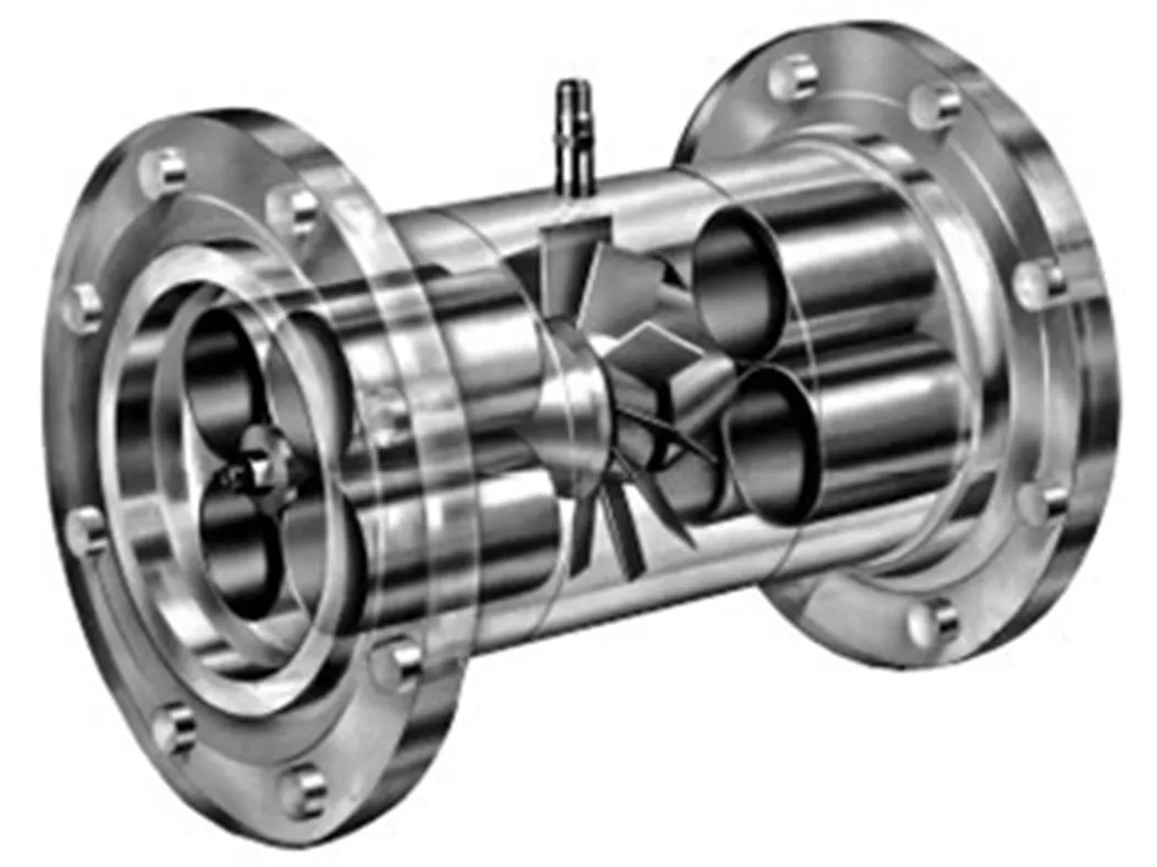
(Image courtesy of sensiaglobal.com)
Turbine Flow Meter – Flow Measurement
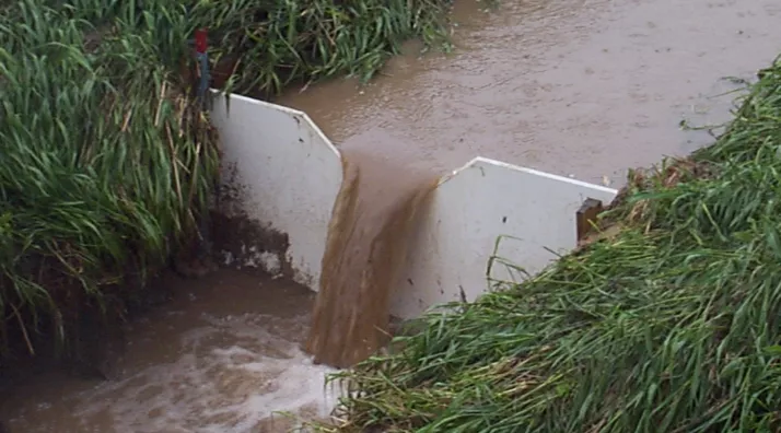
(US Geological Survey)
V-notch Wier – Flow Regulator

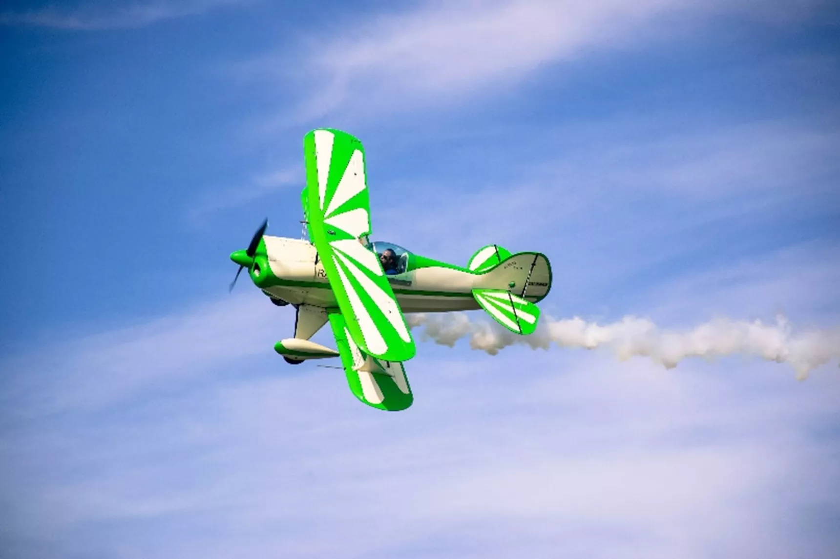
(Image courtesy of studentpilotguide.co.uk)
Aircraft Pitot Tube – Airspeed Measurement Device
Wind Tunnels
Mainly used for aerodynamic research, wind tunnels allow a thorough understanding of the forces exerted as air flows over and around airfoils and vehicles. By simulating airflow conditions and incorporating scale models, they help quantify the performance of large vehicles in a small space. Low- and high-speed tunnels can simulate conditions experienced in a wide range of operating conditions, including supersonic flight. Also, visualization of the flow trajectories and stagnation areas is done using smoke introduced upstream of a vehicle or small flexible strips of material attached to a vehicle surface.
An early version of the device, circa 1901, was built by the Wright Brothers and used in their Dayton, Ohio bicycle shop. It was instrumental in the development of accurate lift and drag coefficients when existing aerodynamic data didn’t agree with their early glider experiments. (Source: https://www.grc.nasa.gov/www/k 12/airplane/wrights/test1901.html)
One such facility (and likely the most advanced in history) is the recently developed $124MM Honda Automotive Laboratories of Ohio (HALO). It contains a wind tunnel able to generate a simulated wind speed of 192 MPH over full-size vehicles! (Source: https://hondanews.com/en-US/releases/honda-opens-new-world-class-wind-tunnel-in-ohio)
It is quite fitting that two of the most historically significant wind tunnels were developed within about 65 miles of one another.
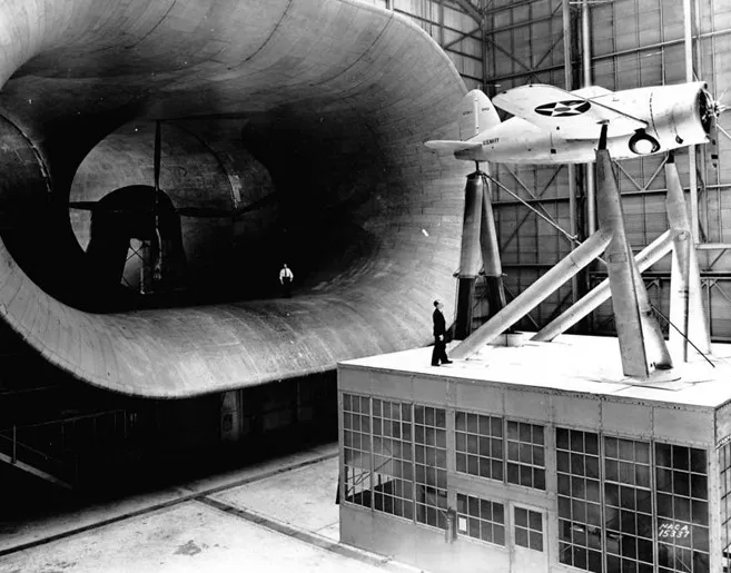
Early (circa 1938) Full Scale NACA Wind Tunnel (Source: National Air and Space Museum)
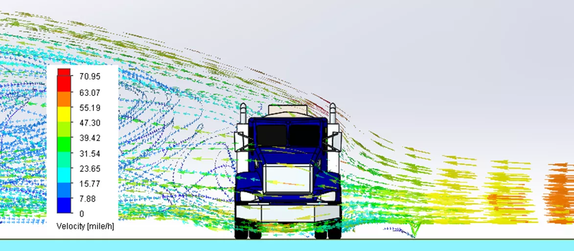
Virtual Simulation of Flow Fields
As one might expect, physical measurement methods can be expensive to build and operate, and they offer only partial information about the entire flow field. Measurement devices usually provide maximum or minimum values of pressure or velocity at a point. Wind tunnels provide good information about the forces involved and help visualize the flow but, except for modern designs, it is difficult to understand what is happening throughout.
This is why numerical analysis and the simulation field called computational fluid dynamics (CFD) is an invaluable resource for those who want to fully understand pressures, forces, velocities, and flow rates within a flow field and optimize product designs by leveraging that understanding. Ever-increasing computing capabilities have allowed program developers to incorporate the fundamental engineering equations describing fluid flow into fast and accurate CFD simulation programs.
CFD results allow virtual comparison of multiple design ideas and examination of the tradeoffs. In the process, the number of prototypes needed to achieve an acceptable design can be significantly reduced.
Common CFD Methods
Many CFD methods are available. As with any simulation tool, there are tradeoffs between speed and accuracy, and some methods are better suited to specific analysis types. Two common methods, Finite Volume (FV) and Lattice Boltzmann (LB), are briefly discussed here. Additional technical information can be found through the links provided within each section.
Finite Volume (FV) Method
Named for the two scientists instrumental in their development, the Navier-Stokes equations describe the balance of mass, energy, and momentum in a flow field. In the FV method, this balance is calculated over the fluid domain, a collection of rectangular fluid volumes (cells) or elements. The FV method uses a Reynolds Averaged Navier-Stokes (RANS) solution. The solution converges when the Navier-Stokes equations are balanced across all cells/elements and the entire fluid domain.
An important aspect of any CFD simulation is the consideration of fluid turbulence and how the boundary layer (flow close to the walls) is represented. Capturing the entire boundary layer explicitly can only be done with direct numerical simulations (DNS), which are computationally expensive. FV methods account for turbulence through secondary wall functions, as opposed to directly modeling the turbulent flow.
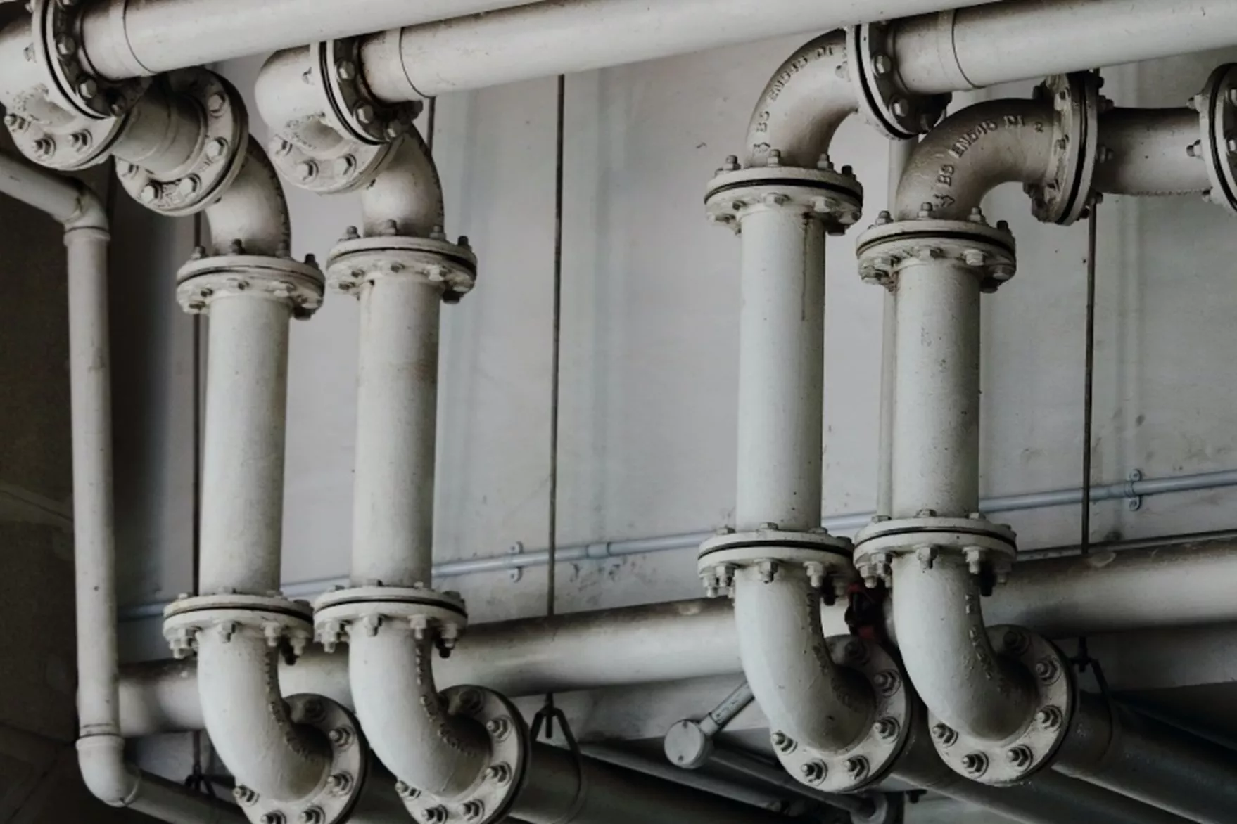
The FV method is well suited to steady state and low-frequency transient thermal simulations, especially those involving electronics cooling. Automatic or user-defined time stepping is available. Some programs even have virtual representations of electronic components which permit efficient and accurate temperature distribution predictions. Applications that are handled well by this method also include solutions of flow through pipes and valves. Sliding mesh functionality in rotating regions permit the prediction of fluid-handling devices such as fans, turbines, pumps, and turbochargers.
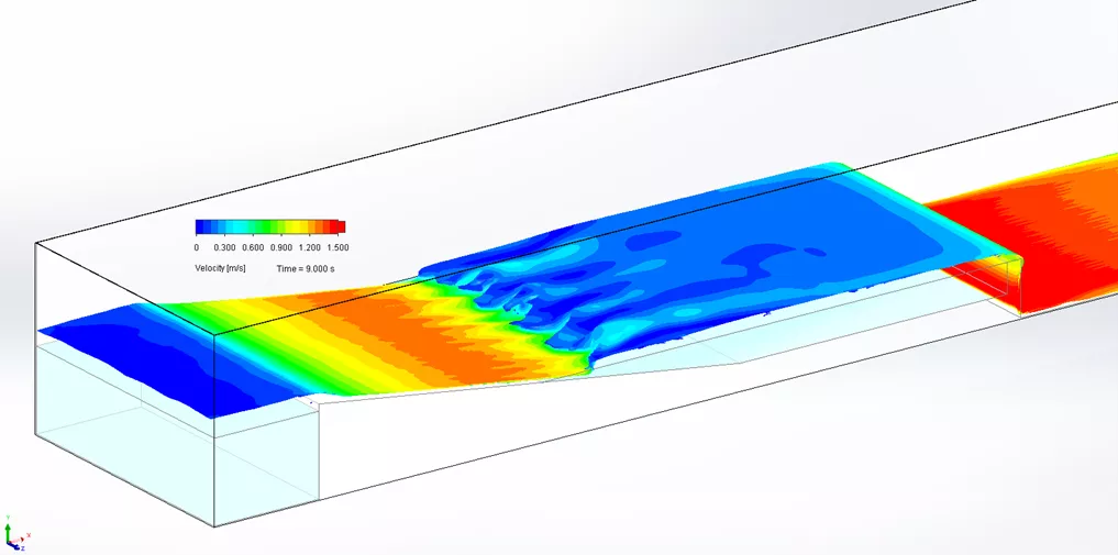
Finally, hydrology simulations of open channel flow in weirs and dam breaks can be effectively handled with supplemental functionality known as the volume of fluid (VOF) method. This tool permits establishing a free surface interface between the liquid and gas based on differential densities.
![]() GoEngineer Simulation Webinar: SOLIDWORKS Flow Simulation: How Can CAD Integrated CFD Tool fulfill your Analysis Needs
GoEngineer Simulation Webinar: SOLIDWORKS Flow Simulation: How Can CAD Integrated CFD Tool fulfill your Analysis Needs
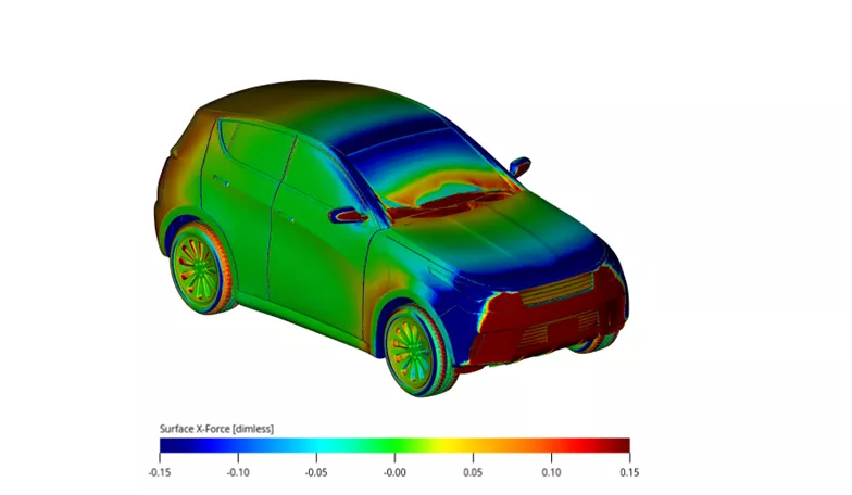
Lattice Boltzmann (LB) Method
While the FV method considers a collection of subdivided fluid volumes, the Lattice-Boltzmann method treats the flow field as a set of particles grouped in a lattice arrangement. Geometry is captured with a body-fitted mesh, which allows small movements of the bodies under study. The fluid particles (nodes) on the lattice capture the physical space occupied by the flow field. The Boltzmann equation used in this method represents a distribution function that determines the probability of a particle to exist at a specific time and location with a given momentum. The result is that microscopic fluid particle interaction is captured on a mesoscopic scale. Macroscopic quantities, such as density, momentum, shear stress, etc., are calculated by integration of the distribution function. The resulting time- and space-averaged flow conditions satisfy the Navier-Stokes equations mentioned above.
Regarding turbulence, LB methods use a combination of directly capturing the turbulent boundary layer within the lattice up to a point through large eddy simulations (LES). At locations very close to the wall, these methods also switch to wall functions.
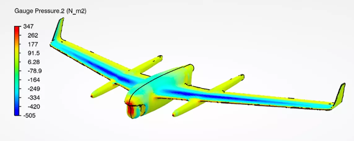
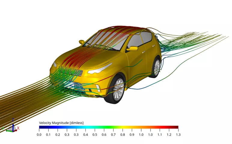
The LB method is ideally suited for transient solutions. In fact, they always solve the problem as transient since the probability distribution function is time- and location-dependent. This, together with advanced turbulence modeling and the ability to capture the boundary layer more accurately, makes this method well suited to external aerodynamic simulations.
![]() Dassault Systèmes SIMULIA Webinar: Overview of Lattice-Boltzmann based CFD for External Aerodynamics
Dassault Systèmes SIMULIA Webinar: Overview of Lattice-Boltzmann based CFD for External Aerodynamics
Computational Cost/Benefit
FV Method – time averaged steady state or transient solutions. The mesh can be time-consuming to create due to the way the cells are split into polygons to define the solid/fluid boundary. However, these simulations can be solved relatively quickly due to the somewhat relaxed overall cell count requirement.
LB Method – always transient solutions. LBM can capture moving geometries, turbulence, and flow separation, but this comes with the cost of lengthy solve times. High-frequency flow behavior is accurately captured, which is important for acoustics analysis. With very little additional effort by the analyst, the surface mesh representation can capture important small details that affect the flow.
CFD Consulting Solutions
GoEngineer CFD Consulting
Those who aren't ready to bring CFD software, hardware, and staff in-house can still enjoy all the benefits of fluid simulation (i.e. faster design iteration, better product performance, less prototyping waste, etc.) by engaging CFD consulting services. GoEngineer's advanced simulation team includes dedicated CFD analysts who will expertly leverage the latest simulation software on powerful hardware on your behalf. We are available for short-term and long-term analysis work, test correlation, CAE methodology development, and more. We're committed to delivering quality results, on time, with excellent communication from start to finish.

SOLIDWORKS CFD Solutions
SOLIDWORKS Flow Simulation
SOLIDWORKS Flow Simulation offers a RANS FV solution suited to general low-frequency transient, thermal calculations, and incorporates a cartesian mesh routine. At the solid interfaces, the cells are further subdivided to create complex polygons. Since it works directly within the SOLIDWORKS interface, it is possible to leverage the CAD geometry to easily conduct parametric studies including “what-if”, goal optimization, and design of experiments (DOE) methods. Turbulence modeling is accomplished using the k-epsilon (turbulent kinetic energy – turbulent dissipation) method, one of the more commonly used methods. (Source: https://www.cfd-online.com/Wiki/K-epsilon_models).
SOLIDWORKS Plastics
A design for manufacturing solution to check the ability of plastic products to be produced using the injection molding process, SOLIDWORKS Plastics contains two simultaneous RANS CFD solutions: the non-Newtonian fluid flow of the molten plastic within the mold and the flow of coolant in the cooling channels with heat transfer effects. SOLIDWORKS Plastics also works directly with CAD geometry, which allows great flexibility to accomplish a thorough design exploration. All aspects of the molding process are available for simulation (fill, pack, cool), and it is possible to approximate the final warped shape of the part after it is ejected from the mold and cools further to room temperature.
3DEXPERIENCE Platform CFD Solutions
3DEXPERIENCE FLUIDS
3DEXPERIENCE FLUIDS Fluid Dynamics Engineer is a RANS solution that, like SOLIDWORKS Flow Simulation, is suitable for general low-frequency transient and thermal applications. Meshing is done by first fitting a surface mesh to the solid bodies, followed by a hex-dominant filling of the fluid volume, thereby allowing the program to accurately capture the solid boundaries and even simulate small body movements – a pseudo fluid-structure interaction function. It offers two additional turbulence modeling methods above what SOLIDWORKS Flow Simulation has, including the Spalart-Allmaras method, developed specifically for aero drag applications (Source: https://turbmodels.larc.nasa.gov/spalart.html) and the k-omega (turbulent kinetic energy – turbulent dissipation rate) method.
3DEXPERIENCE PLASTICS
Like SOLIDWORKS Plastics, 3DEXPERIENCE PLASTICS Plastic Injection Engineer allows part designers to check for injection molding manufacturability while working with designs on the 3DEXPERIENCE Platform. It offers a guided simulation setup process to simulate the complete injection molding of plastic parts and reduce mold rework. The solver leverages the RANS CFD calculations to represent the flow of molten plastic and the cooling fluids that are simultaneously present in the process. For solving simulations, it includes 8-core local/cloud compute capability.
Dassault Systèmes Desktop CFD Solutions
XFlow
XFlow uses an LBM approach to obtaining a solution. This functionality makes it easy to track moving surfaces and therefore, handle applications where fluid-structure interaction is important to capture. XFlow currently supports gearbox lubrication simulations to capture the flow of oil to components and determine where the wetted areas exist - a direct indicator of lubrication effectiveness.
PowerFLOW
High-end aerodynamic and aeroacoustics simulations are the key areas supported by PowerFLOW, which also uses the LBM approach to obtain complex transient solutions. The transportation industry uses PowerFLOW extensively to determine ways to reduce drag and cabin noise. Aircraft and automotive design times are shortened and expensive prototypes are reduced when this technology is used.
Conclusion
Our ability to understand the nature of flowing fluid continues to grow, especially in virtual simulations. Multiple techniques are currently available, and it is possible to tailor your selection based on the application at hand and available budget. Regardless of the chosen method, GoEngineer has the sales and technical expertise to help pick the best path forward. Contact us for more information!
Related Articles
SOLIDWORKS Flow Simulation Design of Experiments and Optimization Study
Understanding Flaps Using SOLIDWORKS Flow Simulation Parametric Study
SOLIDWORKS Flow Simulation Recirculating System Scenario
Understanding the Tesla Valve Using SOLIDWORKS Flow Simulation

About Kurt Kurtin
Kurt has been using SOLIDWORKS simulation tools since 2000, and has been providing simulation support as an applications engineer since 2005. His simulation experience lies in structural, thermal, fluid, seismic, and kinematic rigidbody dynamics, and has training and certification in all SOLIDWORKS Simulation products.
Get our wide array of technical resources delivered right to your inbox.
Unsubscribe at any time.