SOLIDWORKS Flow Simulation Coefficient of Drag
In this article, we discuss how to add a coefficient of drag goal into a flow simulation project. Derived from the principle of Bernoulli’s equation, SOLIDWORKS Flow Simulation can help us obtain this value quickly by utilizing our setup parameters.
Setup
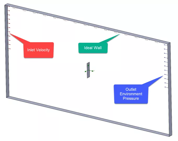
We created an internal volume where the fluid enters via a constant velocity and exits due to environmental pressure. An ideal wall boundary condition was added to the top to prevent the fluid from slipping. In SOLIDWORKS Flow Simulation, we can make use of dividing the computational domain by half using the symmetry condition ensuring the conditions of flow are equal on both the top and bottom halves.
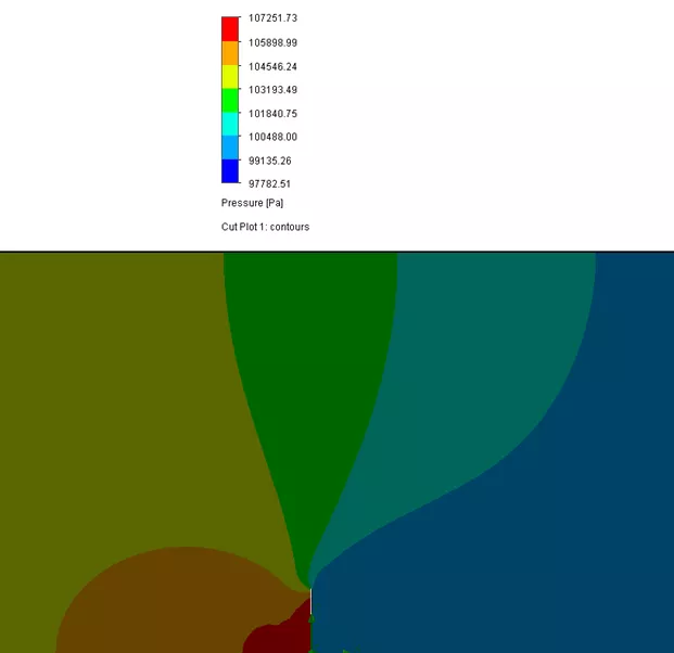
A Cut Plot can display the pressure field interacting with the wall. In this example, the fluid entering from the left shows greater pressure at the front versus the backside.
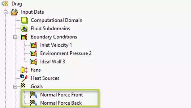
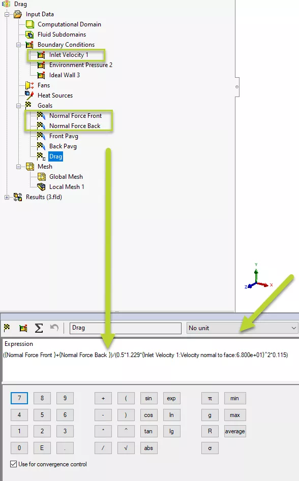
For Goals, we can add surface goals to measure the total normal force on the flat plate (front and back).
Coefficient of Drag Equation Goal
To set up the equation, we first need to reference Bernoulli’s equation and substitute some of the unknowns based on our initial setup in SOLIDWORKS.
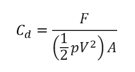
F will be determined from the normal force goals.
![]() is the density of the fluid and V is the fluid velocity, which is obtained from our boundary condition.
is the density of the fluid and V is the fluid velocity, which is obtained from our boundary condition.
A will be the surface area of the front flat face. This value can be obtained by measuring the surface area directly in the model.
In SOLIDWORKS Flow Simulation, we will add an equation goal by right-clicking Goals > Insert Equation Goal. In the dialog, selecting items from our study tree can replace the known values in the equation. The equation goal also allows us to select the type of unit as in a dropdown. Since the drag coefficient is unitless, No Unit is selected.
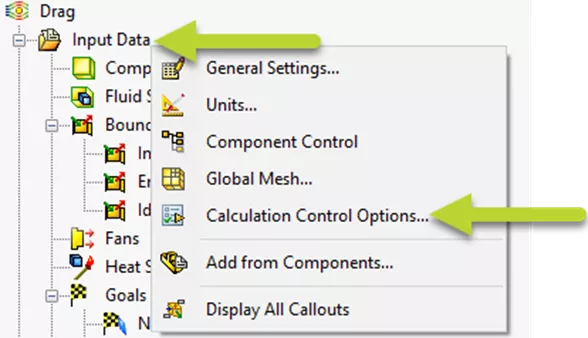
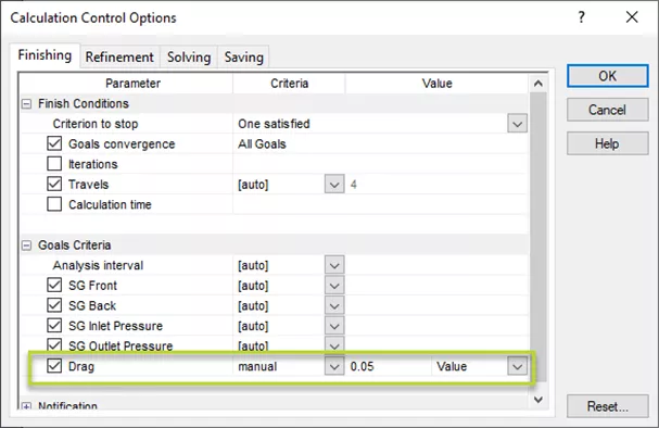
Before solving the study, we will right-click Input Data > Calculation Control Options and specify a criterion for when this goal converges. To enter a value, we can switch the auto setting to manual via the Criteria dropdown.
Results
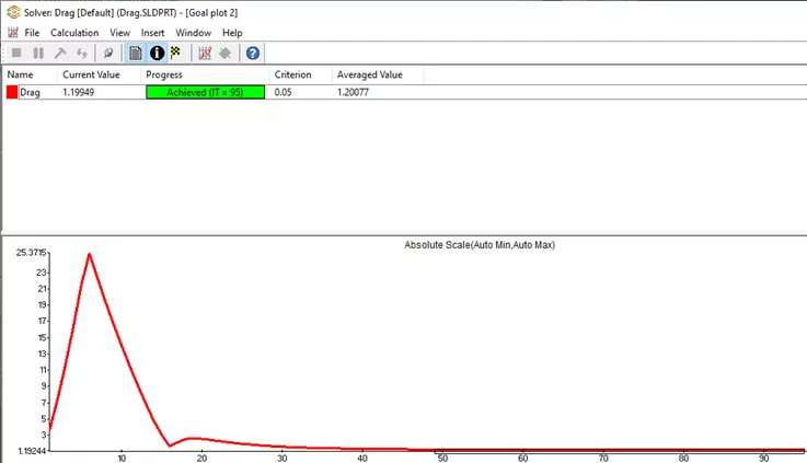
During the analysis, we can add a goal plot to review the progress of the drag coefficient equation.
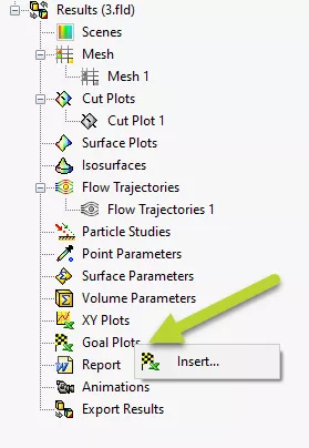
The goal value can also be obtained in the results section by right-clicking Goal Plots > Insert...
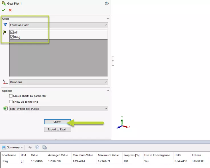
By selecting the goals, the Show button will list this value in a table.
I hope you found this quick SOLIDWORKS Flow Simulation tutorial helpful.
![]() To learn more about this subject and to see a live demonstration, check out our YouTube video: SOLIDWORKS Flow Simulation – Drag Equation Goal.
To learn more about this subject and to see a live demonstration, check out our YouTube video: SOLIDWORKS Flow Simulation – Drag Equation Goal.
More SOLIDWORKS Flow Simulation Tutorials
Intro to Creating Lids in SOLIDWORKS Flow Simulation
SOLIDWORKS Flow Simulation: How Many CPU Cores Do You Need?
Calculating the Center of Pressure in SOLIDWORKS Flow Simulation
SOLIDWORKS Flow Simulation Heat Pipes Explained

About Jackie Yip
Jackie Yip is a Technical Support Engineer at GoEngineer. When Jackie isn’t assisting customers or teaching a SOLIDWORKS Essentials class, he enjoys road biking and keeping up on the latest tech trends.
Get our wide array of technical resources delivered right to your inbox.
Unsubscribe at any time.