Intro to Creating Lids in SOLIDWORKS Flow Simulation
In order to run an internal flow analysis in SOLIDWORKS Flow Simulation, we need to be working with an enclosed volume. If our model has openings, then we need to close them by adding bodies called lids. SOLIDWORKS Flow Simulation includes a tool called Create Lids that will, as the name suggests, create lids automatically.
Accessing the Create Lids Tool
Access Create Lids via Tools > Flow Simulation > Tools > Create Lids.
Alternatively, select the Create Lids icon under the Tools dropdown in the Flow Simulation CommandManager tab.
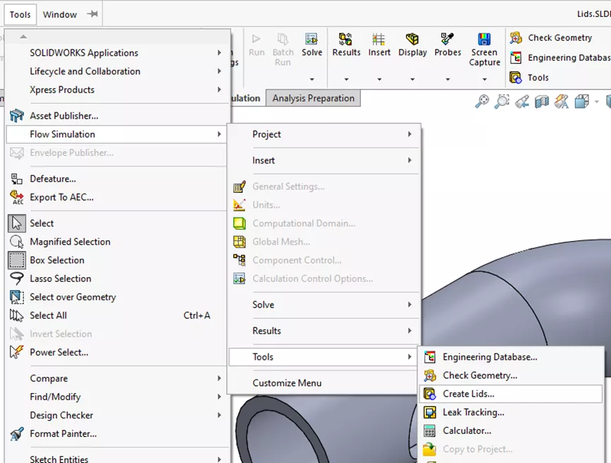
Figure 1: Tools Dropdown Create Lids Location
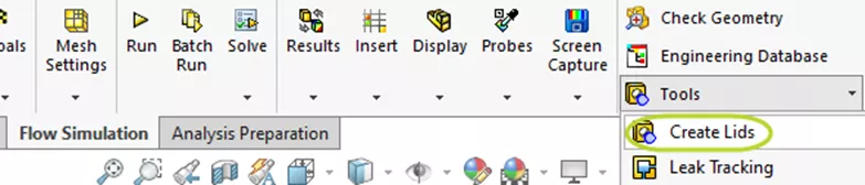
Figure 2: Create Lids Button in CommandManager
Opening the Create Lids PropertyManager prompts us to select a planar face with openings, to which lids should be added.
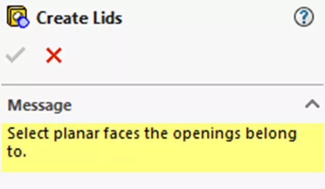
Figure 3: Create Lids PropertyManager
After selecting a face, the size and shape of the lids are determined automatically. Modify the thickness by toggling the Adjust Thickness button.
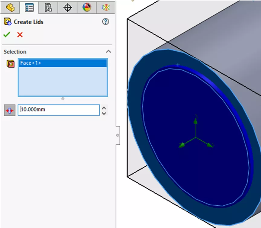
Figure 4: Create Lids PropertyManager After Selecting Face
This creates a Lid feature in your FeatureManager Design Tree. Lids are separate bodies, so it will also add a new body to the Solid Bodies folder at the top of the FeatureManager Design Tree.
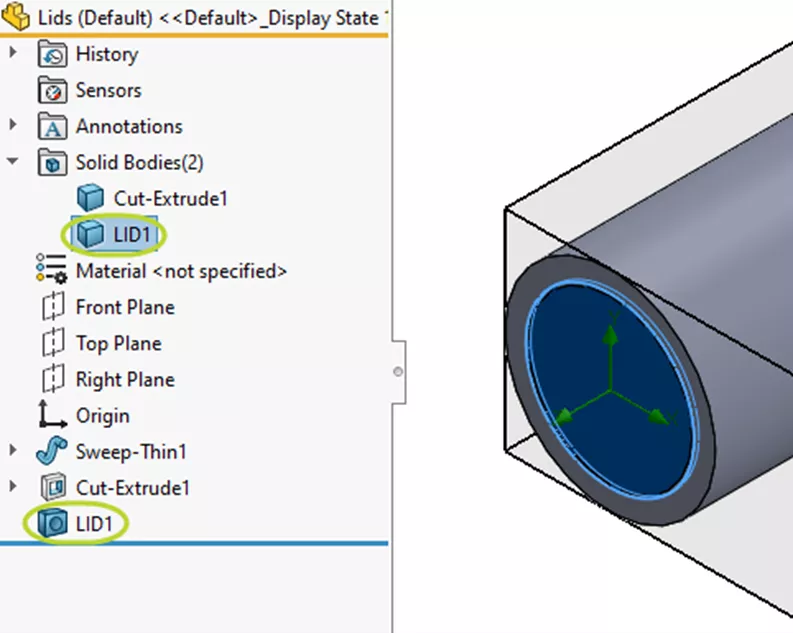
Figure 5: FeatureManager Design Tree with Lid Feature and Body
Manually Creating Lids
We cannot automatically create lids for openings in non-planar faces. In these cases, we must create lids manually.
A common way to do this is with the Boss Extrude feature. To start, create a plane near the opening.
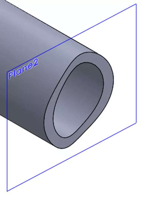
Figure 6: Reference Plane Near Opening in Non-Planar Face
Then, create a sketch on the plane. Use Convert Entities or Offset Entities to capture the shape of the opening. It might be necessary to zoom in to ensure you are selecting all the edges of the opening and that there aren't any gaps.
Once you have the sketch, extrude it to create a lid. Uncheck Merge result to create a distinct body.
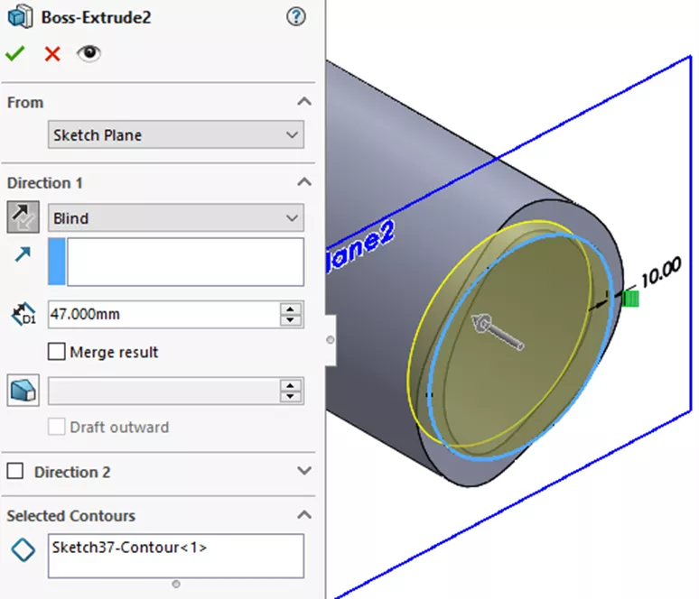
Figure 7: Boss Extrude PropertyManager for Lid
The lid should overlap the surrounding geometry slightly in order to avoid problematic line-to-line contact. However, make sure not to extrude too far into the interior of the model, so as not to affect the fluid volume.
I hope you found this introduction to creating lids in SOLIDWORKS Flow Simulation helpful. Check out more tips and tricks below.
![]() This article is a companion to this SOLIDWORKS Flow Simulation Tutorial
This article is a companion to this SOLIDWORKS Flow Simulation Tutorial

SOLIDWORKS CAD Cheat Sheet
SHORTCUTS ⋅ MOUSE GESTURES ⋅ HOT KEYS
Our SOLIDWORKS CAD Cheat Sheet, featuring over 90 tips and tricks, will help speed up your process.
More SOLIDWORKS Flow Simulation Tutorials
SOLIDWORKS Flow Simulation: How Many CPU Cores Do You Need?
Calculating the Center of Pressure in SOLIDWORKS Flow Simulation
SOLIDWORKS Flow Simulation Heat Pipes Explained
SOLIDWORKS Flow Simulation: Adding Local Mesh Control
SOLIDWORKS Flow Simulation FEA Load Transfer: Setup, Results, & Static Study

About Lauren McGarry
Lauren McGarry is a Certified SOLIDWORKS Expert based out of San Diego, California. She earned her Bachelor of Science degree from Case Western Reserve University and has been with GoEngineer as a Technical Support Engineer since 2016.
Get our wide array of technical resources delivered right to your inbox.
Unsubscribe at any time.